

From the Deutz TCD 2012 common rail fuel system to the closed-loop travel pumps, this 994-page Bomag BW 190 AD-4, BW 202 AD-4, BW 203 AD-4 service manual pdf (OEM 008 914 68) walks the entire tandem vibratory roller end to end. Detailed hydraulic schematics map the flow through the vibration and steering circuits, while complete electrical diagrams trace the EMR3 engine control logic. Troubleshooting charts isolate pressure loss in the axial piston swash-plate pumps, backed by dedicated teardown procedures for the AD-drum and oscillating articulated joint. When reassembling the drive components, you will torque the starter mounting screws to exactly 60 Nm and verify the carbon brushes meet the 5 mm minimum length. Guessing charge pressures on a closed-loop hydrostatic circuit will destroy a pump before the mat even cools, so print out the bookmarked pages you need and take the real factory data straight to the bench.
Complete the set for your BW 190 AD-4, BW 202 AD-4, BW 203 AD-4
- Operator Manual: Bomag BW 161 AD-4, 202 AD-4, 161 ADH-4, 203 AD-4 Operator Manual
- Operator Manual: Bomag BW 161 ADH-4, 202 AD-4, 203 AD-4 Operator Manual
- Repair Manual: Bomag BW 161 AD-4, 202 AD-4 Service Training — Wiring Diagrams
What's Inside This Bomag BW 190 AD-4, BW 202 AD-4, BW 203 AD-4 Manual
| System | Pages | Key Topics |
|---|---|---|
| General | 9-34 | Introduction, Safety Regulations, Tightening Torques |
| Pivot Steered Tandem Rollers | 35-38 | Heavy Vibratory Rollers, Articulated |
| Technical Data | 39-48 | Weights, Travel Characteristics, Drive, Brakes, Steering, Exciter System |
| Maintenance | 49-58 | Fuels and Lubricants, Table of Fuels and Lubricants, Running-In Instructions, Maintenance Table |
| Electrics | 59-76 | Inductive Proximity Switch, B63, Angle Sensor on Travel Control Lever, B39, Pressure Sensor in Water Tank, Level Sensor in Diesel Tank |
| Electronic Modules | 77-194 | Bem, Bomag Evib-Meter, Electrics Module A03, Electrics Module A68, Electrics Module A71, Electric Module A72, Old Design |
| Speedometer Module | 195-198 | Manual Testing, Teaching the Module |
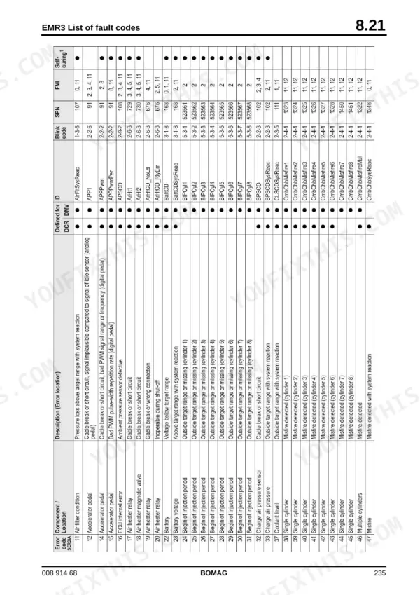
| Engine Electrics | 199-324 | EMR3 System Components, Pin Assignment of Engine Control EDC16 / EMR3, Rotary Speed Sensor for Camshaft, Rotary Speed Sensor for Crankshaft, Rail Pressure Sensor |
| Hydraulics | 325-380 | Hydraulic Circuit, Travel Pump, A4VG56 Hw, Vibration Pump, A10VG45 Ez, Axial Piston Swash-Plate Principle, Troubleshooting Axial Piston Pumps, Travel Motor 51C060 |
| Tests and Adjustments | 381-402 | Special Tools, Checking the Rotation Speeds, Pressure Tests in the Travel Circuit, Checking / Adjusting the Neutral Positions of the Travel Pump |
| Trouble Shooting | 403-420 | Travel System, No Vibration, Steering System, Axial Piston Pumps, Engine Problems |
| Flushing and Bleeding | 421-454 | Special Tools for Flushing, Flushing - General, Flushing Schematic for Front Drum Drive, Flushing the Front Drum Drive, Flushing Schematic for Rear Drum Drive System |
| Engine | 455-502 | Diesel Engine, Engine Description Tcd 2012, Lubrication Oil Circuit Tcd 2012 / 2013, Coolant Circuit Tcd 2012 / 2013, Fuel System Tcd 2012 / 2013 |
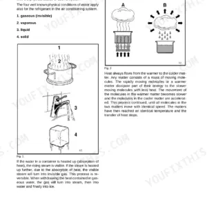
| Air Conditioning System | 503-546 | Physical Basics, Refrigerant R134a, Compressor Oil / Refrigeration Oil, Working Principle of the Air Conditioning System, Monitoring Devices, Components |
| Replacing the Cab Window Panes | 547-556 | Assembly of Window Panes, Special Tools, Cabin Windows, Auxiliary Materials, Removing and Installing the Window Pane |
| Replacing the Travel Control Cable | 557-574 | Driver's Stand, Wiring Loom, Travel Control Cable, Seat Console |
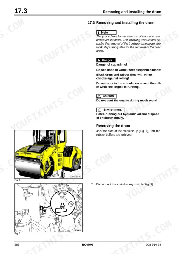
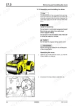
| Drum | 575-620 | Special Tools, Repair Overview AD-drum, Removing and Installing the Drum, Dismantling the AD-drum, Ad/Ap Disassembling, Assembling the Exciter Unit, Assembling the AD-drum |
| Oscillating Articulated Joint | 621-644 | Repair Overview Oscillating Articulated Joint, Removing - Disassembling the Oscillating Articulated Joint, Assembling the Oscillating Articulated Joint |
| Suppliers Documentation | 645-946 | Travel Pump, Vibration Pump, Drum Drive, Drum Reduction Gear, Vibration Motor, Steering Valve |
| Circuit Diagrams | 947-994 | Hydraulic Diagram 920 100 61, Wiring Diagram 920 100 09 |
Quick Reference Specifications
| Specification | Value | Page |
|---|---|---|
| Tightening torque for starter mounting screws | 60 Nm | p. 324 |
| Tightening torque for terminal 30 | 24 Nm | p. 324 |
| Tightening torque for 5/8" thread | 13.6 - 20.3 Nm | p. 515 |
| Tightening torque for 7/8" thread | 35.3 - 42.0 Nm | p. 515 |
| clamping screws final tightening torque | 8.5 Nm | p. 606 |
| clamping screws intermediate tightening steps | 3 Nm and 5 Nm | p. 606 |
| Max. torque for pressure cut-off adjustment screw | 2 Nm | p. 737 |
| Engine Oil Capacity (with filter) | 10.5L | p. 54 |
| Fuel Tank Capacity | 200L | p. 54 |
| Coolant Capacity | 16L | p. 54 |
| Hydraulic System Oil Capacity | 60L | p. 54 |
| Exciter Shaft Oil Capacity (BW 190 AD-4) | 8.5L | p. 54 |
Bomag BW 190 AD-4, BW 202 AD-4, BW 203 AD-4 Common Problems This Manual Covers
Bomag BW 190 AD-4, 202 AD-4, and 203 AD-4 starter motor clicks but engine fails to crank.
Inspect the starter motor carbon brushes. Replace the brushes if they measure under the 5 mm minimum length on page 318. Clean the connections and tighten the Terminal 30 retaining nut to exactly 24 Nm before testing the starting circuit.
Manual Section: Engine Electrics p. 318Both drums stop vibrating completely or static linear load fails to meet density requirements.
Check the vibration motor coupling hub clamping screws. Torque these screws to 35 Nm as shown on page 618. Drain the exciter shaft housing and refill with 8.5L for the 190 model or 9.5L for the 202 and 203 models.
Manual Section: Drum p. 618Roller loses travel power on steep grades or machine creeps forward with travel lever in neutral.
Check the hydraulic system oil level to ensure it meets the full 60L capacity requirement on page 54. Inspect the travel pump linkages and manually adjust the neutral position so the machine stops completely when the control lever is centered.
Manual Section: Maintenance p. 54Intermittent cranking during cold starts or noticeable grinding noise coming from the engine flywheel area.
Remove the starter motor and inspect the mounting hardware for wear. Reinstall the unit and torque the starter mounting screws to exactly 60 Nm as outlined on page 324. Verify the engine oil level reaches the 10.5L system capacity.
Manual Section: Engine Electrics p. 324Frequently Asked Questions
What is the procedure for deleting passive faults from the first fault log in the EMR3 system?
To delete passive faults from the first fault log, turn the ignition OFF, press and hold the diagnostics button, and then switch the ignition ON. Continue to hold the button for approximately 10 seconds before releasing it. The deletion process is confirmed by three short flashing pulses. p. 229
What is the M16 screw tightening torque on the drum reduction gear of a Bomag BW 190 AD-4, BW 202 AD-4, BW 203 AD-4?
The M16 screws on the drum reduction gear must be tightened to a torque of 215 Nm. p. 850
What is the correct valve clearance for the TCD 2012 / 2013 engine?
The intake valve clearance is 75° +10° and the exhaust valve clearance is 120° +10°. p. 470
What is the tightening torque for terminal 30 on the starter of the Bomag BW 190 AD-4, BW 202 AD-4, BW 203 AD-4?
The tightening torque for the starter terminal 30 is 24±4 Nm. p. 324
How often should the hydraulic oil filter be changed?
The hydraulic oil filter element should be replaced every 500 operating hours. p. 53
Do I get instant access to this Bomag BW 190 AD-4 Service Manual?
Immediate download of the complete 994-page searchable Service Manual. Access it on any device, from a laptop at your desk to a phone in the field.
Can I print pages of this Bomag BW 190 AD-4 manual for my own shop?
Yes. It prints from any PDF reader, so run off the pages you need for your own repair work.
Reviews
There are no reviews yet.