
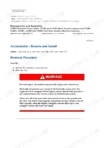
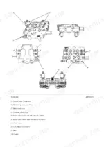
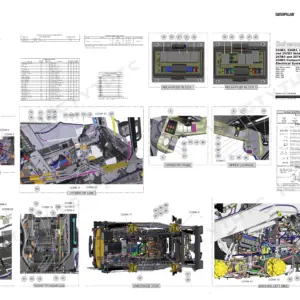
This is the full workshop manual for the Caterpillar 259B3 compact track loader, model years 2011 to 2015. It covers every system on the machine: the C3.4 basic engine, fuel, cooling, air inlet and exhaust, lubrication, the complete hydraulic system, power train, final drives, undercarriage, electrical and starting, operator station, frame, implements and work tools. You get the actual factory test values, not guesswork - fan drive relief at 4725 kPa (685 psi), the 5 micron hydraulic filter spec, filter bypass valve opening at 345 kPa (50 psi), cooler bypass check valve at 172 kPa (25 psi). There is a dedicated Torque Specifications section, plus Service Equipment and Supplies so you know which tools the procedures call for before you pull the machine apart. Electrical schematics (Cat 326-6377, UENR2643) are at pages 2158-2194 and also provided as a separate 37-page PDF. Hydraulic schematics (Cat 326-5540) follow at pages 2195-2206.
What's Inside This Caterpillar 259B3 Repair Manual
| System | Pages | Key Topics |
|---|---|---|
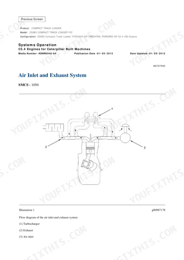
| Air Inlet and Exhaust System | 2 | Air Cleaner, Turbocharger, Exhaust Manifold |
| Basic Engine | 47 | Cylinder Head, Camshaft, Pistons |
| Cooling System | 373 | Radiator, Water Pump, Thermostat |
| Electrical and Starting System | 474 | |
| Engine Arrangement | 497 | Engine Mounts, Engine Assembly |
| Frame and Body | 579 | Frame, Guards, Body Panels |
| Fuel System | 602 | Fuel Injection Pump, Injectors, Fuel Filter, Fuel Lines |
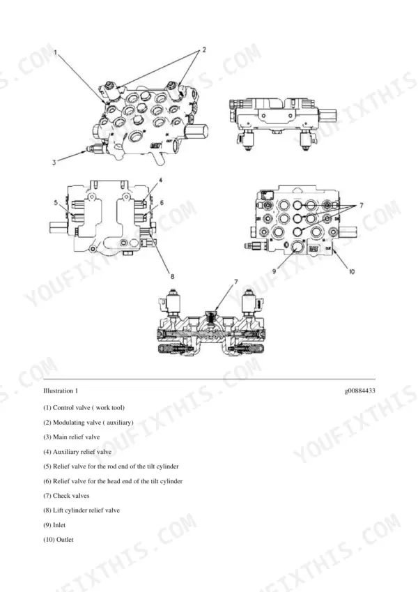
| Hydraulic System | 690 | Control Valve |
| Implements | 1104 | Loader Linkage, Coupler, Bucket |
| Lubrication System | 1155 | Oil Pump, Oil Pan, Oil Filter |
| Machine Arrangement | 1200 | Component Locations, Machine Layout |
| Operator Station | 1216 | |
| Power Train | 1638 | Hydrostatic Drive, Final Drives, Drive Motors |
| Service Equipment and Supplies | 1974 | Special Tools, Fluids, Consumables |
| Torque Specifications | 1992 | Tightening Torques, Bolt Specifications |
| Undercarriage | 2040 | Rollers, Idlers, Track Tension |
| Work Tools | 2146 | Attachments, Auxiliary Hydraulics |
| Electrical System Schematics | 2159-2194 | Cab Wiring, Chassis and Engine Wiring, Cid / Mid / Fmi, Electrical Schematic Symbols |
| Hydraulic System Schematics | 2195-2206 | Fluid Power Symbols, Component Locations, Tap Locations, Implement Pilot Control, S-Turn Resolver Block |
Quick Reference Specifications
| Specification | Value | Page |
|---|---|---|
| Fan drive gear motor relief valve setting | 4725 +/- 100 kPa (685 psi) | p. 702 |
| Hydraulic oil filter rating | 5 micron | p. 703 |
| Filter bypass valve opening pressure | 345 kPa (50 psi) | p. 704 |
| Filter bypass switch closing pressure | 290 +/- 15 kPa (42 psi) | p. 704 |
| Hydraulic oil cooler bypass check valve opening | 172 kPa (25 psi) | p. 711 |
Caterpillar 259B3 Common Problems This Manual Covers
Hydraulic hose leaks with metal particles showing up in drained oil
The Hydraulic System section gives the test values to confirm the filter is doing its job: 5 micron rating, bypass valve opening at 345 kPa (50 psi), bypass switch closing at 290 kPa (42 psi) (pages 703-704), and the Power Train section carries the hydraulic oil filter group specification (page 1769). Test, find the wearing component, replace, then flush before the debris circulates.
Manual Section: Hydraulic System p. 704Track tension sag out of range, tracks slipping off rollers
The Undercarriage section explains how the track adjuster and recoil group sets tension (page 2044) and covers recoil spring and track adjuster removal and installation (page 2107); the tension check itself is referenced to the Operation and Maintenance Manual. Replace a leaking adjuster immediately - a track run loose for a week costs more in sprockets and rollers than the part ever will.
Manual Section: Undercarriage p. 2044Final drive oil contaminated with metal chips
The Power Train section has the hydrostatic piston motor removal (page 1816) and the final drive bench disassembly and assembly procedures (pages 1834 and 1864), including bearing and seal removal. Chips in the drive oil mean the wear has already started, so open it up now instead of waiting for the drive to lock on a slope.
Manual Section: Power Train p. 1834Hydraulic oil running hot or cooling fan not pulling its weight
The Hydraulic System section covers testing the fan drive gear motor against its relief setting of 4725 kPa (685 psi) and checking the oil cooler bypass check valve, rated at 172 kPa (25 psi). A stuck bypass valve sends hot oil around the cooler, and the Cooling System section handles the radiator side.
Manual Section: Hydraulic System p. 702Frequently Asked Questions
Does this manual give the torque specs for the final drive bolts on the 259B3?
Yes. There is a dedicated Torque Specifications section plus torque values inside the Power Train and Undercarriage procedures where the bolts actually get touched. That matters on this machine, because loose or worn final drive hardware is a known route to undercarriage damage. Follow the printed value and sequence, not what the last guy left them at. p. 1994
I found metal chips in the drained hydraulic oil. Will this manual help me chase that down?
This is the manual's home turf. The Hydraulic System section walks you through pressure testing against factory values (5 micron filter spec, bypass valve opening at 345 kPa / 50 psi) so you can tell whether the filter has been bypassing dirty oil, then leads you to the worn component. Chips mean something is eating itself - find it before it takes the pump with it. p. 704
Does the manual explain the hydraulic filter warning light on the 259B3?
Yes. The Hydraulic System section (page 704) explains it: the filter bypass switch closes at 290 ± 15 kPa (42 ± 2 psi) differential pressure and lights the indicator on the right control panel, while the bypass valve itself opens at 345 kPa (50 psi). The alert-indicator and reset procedures are not in this book; it refers you to the Operation and Maintenance Manual for those. Service the filter before you clear anything. p. 704
My tracks keep sagging or walking off the rollers. Is track tensioning covered?
Partly. The Undercarriage section explains how the track adjuster and recoil group sets track tension and what goes wrong when it is off (page 2044), and gives remove and install procedures for the recoil spring and track adjuster (page 2107) and the track itself (page 2133). The tension check and sag adjustment are referenced to the Operation and Maintenance Manual, "Track (Rubber) - Inspect/Adjust". Most sag problems on these machines come back to a leaking adjuster or hardware that backed off. p. 2044
Is this the right manual for my machine year, and does it cover the engine too?
It covers 259B3 machines built from 2011 to 2015 and includes the full engine side: Basic Engine, Fuel System, Cooling System, Air Inlet and Exhaust, and Lubrication System, alongside the machine systems. Check your serial number prefix against the manual coverage before ordering if your machine sits right at a model year boundary.
Are electrical schematics included?
Yes. The full 259B3 electrical schematic (Cat 326-6377, UENR2643) is at pages 2158-2194: component and connector locations, CID/MID/FMI codes, and the cab, chassis and engine wiring sheets. The same pages also come as a separate 37-page PDF with your download. p. 2158
Are hydraulic schematics included?
Yes. The hydraulic schematics (Cat 326-5540 plus the KENR9408 and UENR3951 sheets, with fluid power symbols, component locations and tap locations) are at pages 2195-2206, right after the electrical schematic. p. 2195