
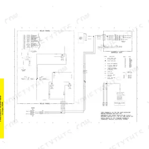
This is the factory repair manual for the Cat 299D and 299D XHP compact track loaders and the 272D and 272D XHP skid steers, 2015-2023, all in one bundle. It covers the machine end to end: hydrostatic drive and final drives, load-sensing hydraulic system with full pressure testing and adjusting procedures, the electrohydraulic joystick controls, engine teardown, undercarriage, and complete electrical and hydraulic schematics. These D-series machines are electronic, so the manual pairs monitor diagnostics with real gauge work - actual relief settings, charge pressures, cycle times, and drift limits with tolerances. If you run a standard-flow machine or a High Flow XPS/XHP unit, both spec sets are in here. This is what the dealer tech reads before quoting you a repair.
Other edition of this manual
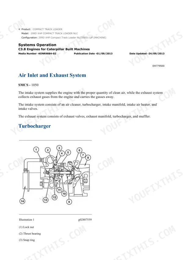
What's Inside This Caterpillar 272D, 299D (D-series) Repair Manual
| System | Pages | Key Topics |
|---|---|---|
| Air Inlet & Exhaust | 2-108 | Air Cleaner, Turbocharger, Muffler, Exhaust |
| Basic Engine | 109-292 | Cylinder Head, Pistons, Crankshaft, Camshaft |
| Cooling System | 293-402 | Water Pump, Radiator, Fan, Thermostat |
| Electrical & Starting System | 403-1032 | Alternator, Starter, Batteries, Monitor, Sensors, Wiring Harness Testing, System Schematic |
| Engine Arrangement | 1033-1102 | Engine Mounting, Supports |
| Frame & Body | 1103-1125 | Main Frame, Guards, Cab Mounts |
| Fuel System | 1126-1214 | Injection Pump, Injectors, Fuel Transfer Pump, Governor |
| Hydraulic System | 1215-1755 | Main/implement Pump, Main Control Valve, Relief Valves, Lift & Tilt Cylinders, Quick Coupler, Cycle Times, Pressure Testing & Adjusting, Electrohydraulic Controls |
| Implements | 1756-1796 | Loader Linkage, Lift Arms, Bucket, Cylinders |
| Lubrication System | 1797-1839 | Oil Pump, Oil Filter, Oil Cooler |
| Machine Arrangement | 1840-1858 | Overall Layout, Component Location |
| Operator Station | 1859-2301 | Cab, Joystick Controls, Seat, HVAC, Display |
| Power Train | 2302-2633 | Hydrostatic Drive, Drive Motors, Charge Pump, Two-Speed, Final Drive |
| Schematic | 2634-2687 | Electrical System Schematic, Hydraulic System Schematic |
| Service Equipment & Supplies | 2688-2706 | Special Tools, Shop Supplies |
| Torque Specifications | 2707-2755 | Fastener Torque Charts |
| Undercarriage | 2756-2848 | Track, Rollers, Idler, Sprocket, Recoil, Track Tension |
| Work Tools | 2849-2892 | Buckets, Attachments, Coupler |
Quick Reference Specifications
| Specification | Value | Page |
|---|---|---|
| All models | ||
| Hydraulic System Operating Temperature | 45° ± 5°C (113° ± 9°F) | |
| Tilt Cylinder Speed (Tilt Forward) | 2.3 ± 0.5 seconds | p. 1396 |
| Tilt Cylinder Speed (Tilt Back) | 2.1 ± 0.5 seconds | p. 1396 |
| Quick Coupler Engagement Time | 3.0 seconds max | |
| Quick Coupler Disengagement Time | 3.0 seconds max | |
| Tilt Cylinder Drift | 3 mm (0.12 inch) in 1 minute | p. 1396 |
| Lift Cylinder Drift | 3 mm (0.12 inch) in 1 minute | p. 1396 |
| Drift Check Test Load | 200 kg (441 lb) | p. 1396 |
| Main Relief Valve Locknut Torque | 18 ± 2 N·m (13.0 ± 1.5 lb ft) | p. 1310 |
| Line Relief Valve Installation Torque | 45 ± 5 N·m (33 ± 4 lb ft) | p. 1310 |
| Pilot Pressure (Accumulator Test, should rise to) | 3500 ± 200 kPa (500 ± 30 psi) | p. 1310 |
| Pilot Pressure (Accumulator Test, decreases slowly until) | 900 ± 100 kPa (130 ± 15 psi) | p. 1310 |
| STD 272D/299D | ||
| Lift Cylinder Speed (Raise), STD 272D/299D | 5.2 ± 0.5 seconds | p. 1396 |
| Lift Cylinder Speed (Lower), STD 272D/299D | 3.7 ± 0.5 seconds | p. 1396 |
| Lift Cylinder Speed (Float), STD 272D/299D | 4.6 ± 0.5 seconds | p. 1396 |
| Line Relief Valve Setting (Lift), STD 272D/299D | 24500 ± 700 kPa (3555 ± 100 psi) | p. 1310 |
| Line Relief Valve Setting (Rack Back), STD 272D/299D | 27600 ± 700 kPa (4000 ± 100 psi) | p. 1310 |
| Line Relief Valve Setting (Tilt), STD 272D/299D | 24500 ± 700 kPa (3555 ± 100 psi) | p. 1310 |
| Line Relief Valve Setting (Auxiliary), STD 272D/299D | 24500 ± 700 kPa (3555 ± 100 psi) | p. 1310 |
| XPS/XHP 272D/299D | ||
| Lift Cylinder Speed (Raise), XPS/XHP 272D/299D | 4.4 ± 0.5 seconds | p. 1396 |
| Lift Cylinder Speed (Lower), XPS/XHP 272D/299D | 3.6 ± 0.5 seconds | p. 1396 |
| Lift Cylinder Speed (Float), XPS/XHP 272D/299D | 4.7 ± 0.5 seconds | p. 1396 |
| Line Relief Valve Setting (Lift), XPS/XHP 272D/299D | 28000 ± 700 kPa (4060 ± 100 psi) | p. 1310 |
| Line Relief Valve Setting (Rack Back), XPS/XHP 272D/299D | 28000 ± 700 kPa (4060 ± 100 psi) | p. 1310 |
| Line Relief Valve Setting (Tilt), XPS/XHP 272D/299D | 25000 ± 700 kPa (3626 ± 100 psi) | p. 1310 |
| Line Relief Valve Setting (Auxiliary), XPS/XHP 272D/299D | 32000 ± 700 kPa (4640 ± 100 psi) | p. 1310 |
| All standard flow models | ||
| Main Relief Valve Setting, All standard flow models | 23000 ± 700 kPa (3335 ± 102 psi) | p. 1310 |
| All High Flow (XPS) and (XHP) models | ||
| Main Relief Valve Setting (All High Flow (XPS) and (XHP) models) | 23000 ± 1000 kPa (3335 ± 145 psi) | p. 1310 |
| All machines | ||
| Charge Pressure (Low Idle) | 2750 ± 200 kPa (399 ± 29 psi) | p. 1310 |
| Charge Pressure (High Idle) | 3100 ± 200 kPa (450 ± 29 psi) | p. 1310 |
| Pilot Pressure for the Work Tool (Low Idle) | 2750 ± 200 kPa (399 ± 29 psi) | p. 1310 |
| Pilot Pressure for the Work Tool (High Idle) | 3100 ± 200 kPa (450 ± 29 psi) | p. 1310 |
| machine | ||
| Hydraulic Oil Temperature (Test Condition) | 50° ± 10°C (122° ± 18°F) | |
| Engine | ||
| High Idle rpm | 2525 ± 50 rpm | p. 1310 |
| Low Idle rpm | 1075 ± 50 rpm | p. 1310 |
| 1 min | ||
| Tilt Cylinder Drift (1829 mm (72 inch) GP Bucket) | 3 mm | p. 1396 |
| 272D/299D | ||
| Standby Pressure | 2100 ± 300 kPa (305 ± 44 psi) | p. 1310 |
| Margin Pressure | 1600 ± 200 kPa (232 ± 29 psi) | p. 1310 |
| Load Sensing Pressure | 21400 ± 700 kPa (3104 ± 101 psi) | p. 1310 |
| High Pressure Cutoff | 28000 ± 400 kPa (4060 ± 58 psi) | p. 1310 |
| 272D | ||
| Drive Pump Pressure (MB/MC), 272D | 38300 ± 2000 kPa (5555 ± 290 psi) | p. 1310 |
| Drive Motor Speed, 272D | 154 ± 15 rpm | p. 1310 |
| Drive Motor Speed (slow mode), 272D | 154 ± 15 rpm | p. 1310 |
| 299D | ||
| Drive Pump Pressure (MB/MC), 299D | 43300 ± 2000 kPa (6280 ± 290 psi) | p. 1310 |
| Drive Motor Speed, 299D | 2390 ± 300 rpm | p. 1310 |
| Drive Motor Speed (slow mode), 299D | 2390 ± 300 rpm | p. 1310 |
| Pilot System | ||
| Pilot Pressure (Low Idle) | 2750 ± 200 kPa (400 ± 30 psi) | p. 1310 |
| Pilot Pressure (High Idle) | 3100 ± 200 kPa (450 ± 29 psi) | p. 1310 |
| STD 272D/299D XPS/XHP 272D/299D | ||
| Charge Pump Minimum Flow | 36.8 L/min (9.72 US gpm) | p. 1310 |
| Work Tool Pump Minimum Flow | 54.3 L/min (14.34 US gpm) | p. 1310 |
| Work Tool Pump Minimum Flow | 74 L/min (19.5 US gpm) | p. 1310 |
| 272D/299D High Flow XPS | ||
| Work Tool Pump Flow at 4140 ± 345 kPa (600 ± 50 psi) | 70 L/min (18.5 US gpm) | p. 1310 |
| Work Tool Pump Flow at 13790 ± 345 kPa (2000 ± 50 psi) | 70 L/min (18.5 US gpm) | p. 1310 |
Caterpillar 272D, 299D (D-series) Common Problems This Manual Covers
Oil leaks at O-ring hose connections in the hydraulic circuit, showing as wet spots, rubbing marks, or bulging hoses.
The Hydraulic System section covers hose routing, connection torque, and O-ring face seal fitting inspection. Fix the clamp or routing causing the rub, not just the hose, or the new one fails the same way in a few hundred hours.
Manual Section: Hydraulic SystemAir conditioning stops cooling, often traced to a failed orifice tube or leakage at the evaporator inlet port.
The Operator Station section covers HVAC service, including orifice tube removal with the 1U-9890 tool and quick disconnect service on the drier. The drier swivel nut spec is 27 N·m (20 lb ft); loose nuts are a common leak point.
Manual Section: Operator StationWeak or slow hydraulics, where the machine feels down on power under load compared to when it was new.
Start with the Pressure Testing and Adjusting procedures in the Hydraulic System section: check standby pressure at 2100 kPa (305 psi), margin at 1600 kPa (232 psi), and high pressure cutoff at 28000 kPa (4060 psi) to isolate pump versus relief valve.
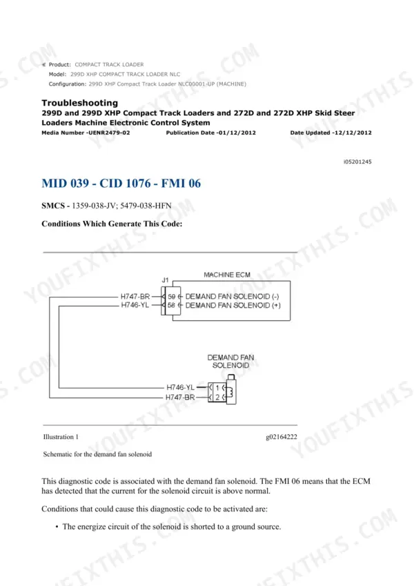
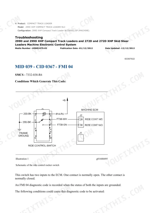
Manual Section: Hydraulic SystemElectrical gremlins, such as intermittent joystick response, sensor faults on the monitor, or a machine that cranks but sets codes.
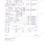
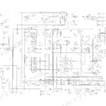
The Electrical and Starting System section gives wiring harness testing procedures and the Schematic section provides the full system diagram, so you can trace a circuit pin to pin instead of swapping ECMs and sensors on a guess.
Manual Section: Electrical & Starting SystemFrequently Asked Questions
Does this manual cover hydraulic pressure testing on the 299D XHP High Flow system?
Yes, and it separates standard-flow from XPS/XHP numbers, which matters. Main relief is 23000 kPa (3335 psi) on all models, but line reliefs differ: auxiliary is 24500 kPa (3555 psi) standard versus 32000 kPa (4640 psi) on High Flow. The Testing and Adjusting section walks through port locations, warm-up to 50°C oil temp, and how to set each valve.
My lift arms drift down with a load. Is there a spec to check against?
There is. The drift check uses a 200 kg (441 lb) test load, and both lift and tilt cylinders are allowed 3 mm (0.12 inch) of movement in 1 minute at operating temperature. More than that and you are into cylinder seals or the control valve, and the Hydraulic System section shows how to isolate which one before you buy parts.
Can I diagnose fault codes shown on the monitor with this manual?
Yes. These are electronic machines with electrohydraulic controls, and the Electrical and Starting System section covers the monitor, sensors, and wiring harness testing, backed by the full electrical schematic. Codes point you to a circuit; the harness tests and schematic let you confirm whether it is a sensor, a wire, or the component itself before replacing anything.
Does it cover track replacement and tension on the 299D?
The Undercarriage section covers tracks, rollers, idlers, sprockets, and the recoil mechanism, including track tension adjustment. Undercarriage is where compact track loaders eat money, so having the removal and installation procedures plus wear-item breakdowns pays for the manual the first time you do tracks in your own shop instead of the dealer's.
Are cycle time specs included so I can tell if my pump is getting weak?
Yes, with tolerances. Lift raise is 5.2 seconds on standard 272D/299D and 4.4 seconds on XPS/XHP machines, both plus or minus 0.5 seconds, measured at high idle (2525 rpm) with oil at temperature. Tilt forward is 2.3 seconds. Slow cycle times against these numbers are your first hard evidence of pump or relief valve trouble.
Reviews
There are no reviews yet.