
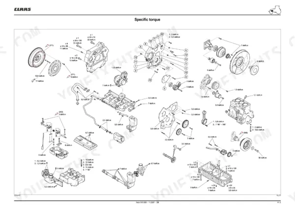
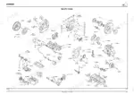
Every one of the 572 pages in this Claas Axion 850 technical manual PDF (OEM #00 11 362 650) is factory rebuild data for the Axion 810, 820, 830, 840, and 850 tractors. The download carries two volumes: this 572-page repair manual and a separate, much larger diagnostic manual that holds the hydraulic and electrical circuit diagrams. The repair volume covers the rear lift, electrohydraulic spool valve, and steering circuit, plus exploded views through the Hexashift and CMatic gearbox modules. Inside: a full torque section, step-by-step measurement procedures for the cylinder head, crankshaft, and common rail injection assembly, and complete teardown coverage of the suspended front axle and rear PTO. Hold the gap between valve bridge bores under 0.1 mm, and fill each epicycloid reducer with exactly 2 litres per side. Your tractor is split in the shop; forum threads won't put it back together. Bookmarked and keyword-searchable, this PDF opens on your phone, tablet, or laptop right at the machine.
What's Inside This Claas Axion 810–850 Manual
| System | Pages | Key Topics |
|---|---|---|
| General | 1-30 | Specific Torque, Blocking Between the Motor Oil Casing/Front Axle Chassis |
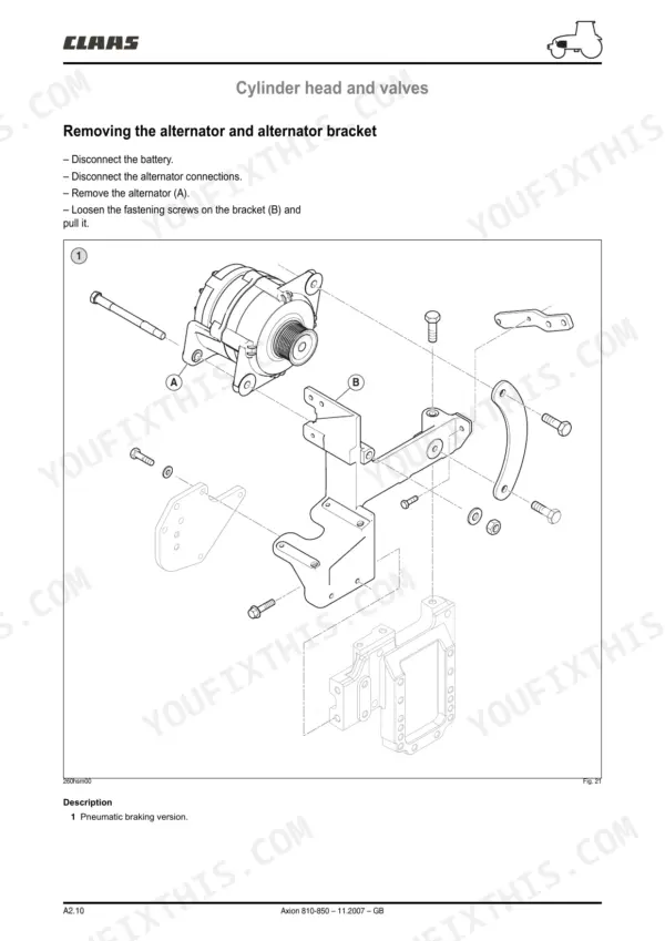
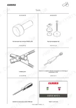
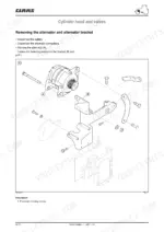
| Cylinder Head and Valves | 31-66 | Local Manufacturing Tool (Injector Socket Extractor, Rocker Caliper, Inspecting Valve Bridges, Inspecting the Rocker Pin, Inspecting the Rockers, Measuring Valve Shrinkage, Cylinder Head Flatness, Measuring Cylinder Head Thickness, Valve Guide Measurement, Measuring the Valve Seat Bore in the Cylinder Head, Measuring the Valve Springs, Measuring the Valves, Inspecting the Turbocharger, Checking the Belt Tensioner Spring, Removing the Alternator and Alternator Bracket, Refitting the Alternator and Bracket, Removing the Viscouc Coupling, Refitting the Viscous Coupling, Removing the Fan Hub and Bracket, Refitting the Fan Hub and Bracket, Removing the Turbocharger, Refitting the Turbocharger, Removing the Turbocharger Rod Linkage, Refitting the Turbocharger Linkage, Removing the Exhaust Manifold, Refitting the Exhaust Manifold, Removing the Cooler and Ducts EGR, Refitting the Cooler and Ducts EGR, Removing the Thermostat Cover, Refitting the Thermostat Cover, Removing the Thermostat Manifold, Removing the Cylinder Head Cover, Refitting the Cylinder Head Cover, Removing the Rocker Arm Assembly, Refitting the Rocker Shaft, Valve Rockers, Method of Adjustment, Removing the Rocker Carrier, Refitting the Rocker Carrier, Removing the Injector Socket, Removing the Cylinder Head, Preparation, Refitting the Cylinder Head, Refitting the Valve and Joint, Refitting the Valve and Gasket, Removing the Valve Seats, Refitting the Valve Seats, Removing the Intake Manifold, Refitting the Intake Manifold, Removing the Air Diffuser, Refitting the Air Diffuser, Removing the EGR Valve, Refitting the EGR Valve) |
| Liners, Pistons and Connecting Rods | 67-88 | Measuring the Counterboring Depth of the Liner Flange in the Block, Measuring the Liner Flange, Measuring Flatness of the Plate and the Plate/Crankshaft Bearing Distance |
| Flywheel, Bearing, and Crankshaft | 89-104 | Measuring the Inner Diameter of the Crankshaft Journals and Bearings, Measuring the Width of Journals and Thrust Bearings, Checking Axial Clearance of the Crankshaft |
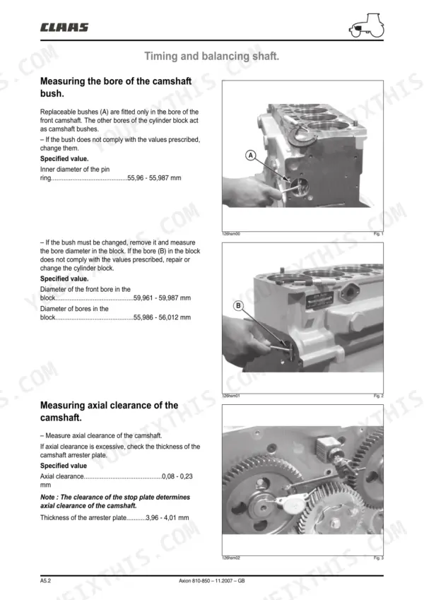
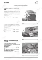
| Timing and Balancing Shaft | 105-120 | Measuring the Bore of the Camshaft Bush, Measuring Axial Clearance of the Camshaft, Measuring the Diameter of the Camshaft Bush and Journals, Measuring the Cam Height |
| Injection Assembly | 121-132 | Removing the Supply Pump, Refitting the Supply Pump, Removing the High Pressure Common Rail, Refitting the High Pressure Common Rail, Removing the Flow Regulators |
| Lubrication System | 133-140 | Oil Filter, Oil Cooler, Engine Oil Pan, Oil Pump |
| Gearbox | 141-242 | Hexashift Module, Revershift Module, Robot-Driven Ranges, 4 Wheel Drive Shaft, Slow Range |
| Gearbox CMatic | 243-290 | Cartridge Cmatic, Line Shafting, Primary Line, Secondary Line, 4 Wheel Drive Shaft |
| General, Drive Pinion, Differential, Rear Power Take-Off, Automatic Brake, Service Brake, Axle Tubes | 291-418 | Gpa 40 Drive Pinion, Differential Lock, Rear PTO Clutch, Automatic Brake, Service Brake, Axle Tubes |
| Suspended Front Axle | 419-486 | Front Axle Removal, Epicycloid Reducer, Joint Unit, Suspension, 4WD Power Take-Off Housing |
| General, Hydraulic Source, Rear Lift, Electrohydraulic Spool Valve, Steering | 487-544 | Hydraulic Source, Rear Lift, Electrohydraulic Spool Valve, Steering Actuator, Steering Unit |
| Cab Lift, Heating/Air Conditioning | 545-572 | Cab Lift Safety, Compressor, Dehydrator Filter, Condenser, Expansion Valve, Motor Fan |
Quick Reference Specifications
| Specification | Value | Page |
|---|---|---|
| Zero play and preload tolerance for tapered roller bearings | 0 + 0,05 mm | p. 214 |
| Preload for shaft clearance in the casing | 0,10 + 0,05 mm | p. 216 |
| Main adjustment clearance | 0.10 ± 0.05 mm | p. 250 |
| Epicycloid reducer oil quantity | 2 litres per side | p. 438 |
| Maximum gap between valve bridge bores | 0.1 mm | p. 33 |
| Rocker axis outer diameter | 19.962 - 20.038 mm | p. 33 |
| Rocker axis wear limit | 19.91 mm | p. 33 |
| Intake valve shrinkage in cylinder head | 0.77 - 1.27 mm | p. 35 |
| Exhaust valve shrinkage in cylinder head | 0.81 - 1.31 mm | p. 35 |
| Maximum acceptable cylinder head straightness error | 0.08 mm | p. 35 |
| New cylinder head thickness | 104.87 - 105.13 mm | p. 36 |
| Minimum acceptable cylinder head thickness | 104.24 mm | p. 36 |
Claas Axion 810–850 Common Problems This Manual Covers
Claas Axion 820 Hexashift creeps in neutral, delayed range engagement, loses drive under heavy load
Check transmission oil level and condition first; burnt or contaminated oil means clutch pack damage in the splitter section. Test pressure at the KV test point to isolate a solenoid valve or jaw clutch fault. During any shaft rebuild, set tapered roller bearing preload to 0 + 0.05 mm, the spec on page 214.
Manual Section: Gearbox p. 141Rattle on engine shutdown, then driveline vibration and constant transmission noise at idle
Split the tractor and inspect the flywheel damper plate; broken damper springs cause the shutdown rattle. Follow flywheel removal in the section starting on page 89 and check crankshaft axial clearance while access is open. Before rejoining, set gearbox input shaft preload in the casing to 0.10 + 0.05 mm per page 216.
Manual Section: Flywheel, Bearing, and Crankshaft p. 89Coolant level keeps dropping with no visible leak, steam from exhaust when warm
Pressure-test the cooling system, then remove the EGR cooler and test it separately; internal cracks dump coolant into the exhaust. Follow EGR cooler removal and refitting from page 31. If the engine has overheated, check cylinder head flatness too; maximum acceptable straightness error is 0.08 mm, detailed on page 35.
Manual Section: Cylinder Head and Valves p. 31Low oil pressure warning at idle, gauge reading disagrees with diagnostic screen value
Compare the dash gauge reading against the diagnostic tool value before replacing parts. A deviation over 0.5 bar means the oil pressure sensor is faulty; replace the sensor. If both readings are low, check oil level and filter condition, then inspect the oil pump and pickup following the procedures from page 133.
Manual Section: Lubrication System p. 133Front axle knocks on full steering lock, play in driveshafts, wobble at road speed
Grease every front axle point first, then jack the axle and check for play in the ball joints, hanger bushes, and driveshaft needle bearings. Replace worn bearings and bushes following the joint unit procedures from page 419. After any epicycloid reducer work, refill each hub with 2 litres of gear oil per side, noted on page 438.
Manual Section: Suspended Front Axle p. 419Frequently Asked Questions
What are the torque specifications for the cylinder head bolts on the CLAAS Axion 810-850?
The cylinder head bolts require a multi-step tightening procedure. Step 1 is 10 daN.m, Step 2 is 15 daN.m, Step 3 is a check after 5 minutes at 15 daN.m, and Step 4 is a final angular tightening of 60° + 10°. p. 59
What is the specified intake valve clearance for the CLAAS Axion 810-850 engine?
The specified intake valve clearance for the engine is 0,36 mm. This check must be performed on a cold engine. p. 53
What is the required oil capacity for the epicycloid reducer on the front axle?
The required oil capacity for the epicycloid reducer is 2 litres per side. p. 438
What is the tightening torque for the front axle fastening screws on the Axion 810-850?
The front axle fastening screws must be pre-tightened to 13 daN.m and then final tightened to 30 daN.m. p. 431
What is the procedure for checking the axial clearance of the crankshaft?
Before removing the crankshaft, place a comparator on the flywheel face or front pulley. Push the crankshaft backwards, set the dial gauge to zero, then push the crankshaft forward to measure the clearance. The specified axial clearance is 0,029 to 0,357 mm. p. 92
How will I receive this Claas Axion 810 Technical Manual?
You download the Technical Manual yourself: 572 pages, searchable PDF, available immediately. Keep a copy on every device you use.
Can I print specific sections of this Claas Axion 810 Technical Manual?
Yes. Print a chapter or just the pages for the job at hand, for use in your own shop. Any home or office printer works.
Reviews
There are no reviews yet.