
Lift control linkage and valve checks are where most tractor rebuilds stall, so this 126-page Fiat 450 shop manual PDF (OEM 603.54.203) gives the hydraulic lift its own section, then widens to the engine, clutch, transmission, axles and electrics of all four 450 variants. Lift diagrams and control linkage schematics show how the pump feeds each valve, backed by a troubleshooting chart and pump output test, while a wiring diagram maps your charging circuit, starter and lights. Clutch work fills a good share of the book, covering both Fiat and LuK units, followed by bevel drive adjustment, differential lock assembly and the power take-off. Measure a 450 Special driven plate against its 8.4 to 9.0 mm range, then torque the lift-to-axle case capscrews to 15.5 kgm (152 Nm). A guessed torque there can crack a housing. Bookmarked and text-searchable, the PDF is bought once and yours to keep for every season you run this 450 in the field.
What's Inside This Fiat 450, 450 DT, 450 Special, 450 DT Special Manual
| System | Pages | Key Topics |
|---|---|---|
| General | 1-6 | General Instructions |
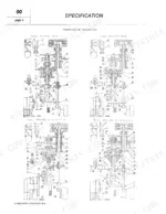
| Specification | 7-16 | Charging System, Starter Motor, Battery - Fuses, Lighting - Signals - Accessories, Switches - Turn Signal Indicator Switch, Wiring Diagram |
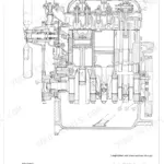
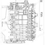
| Engine | 17-32 | Illustrations (Sections Through Oil Pump and Water Pump, Cooling System Diagram, Lubrication System Diagram, Longitudinal Section Through Engine) |
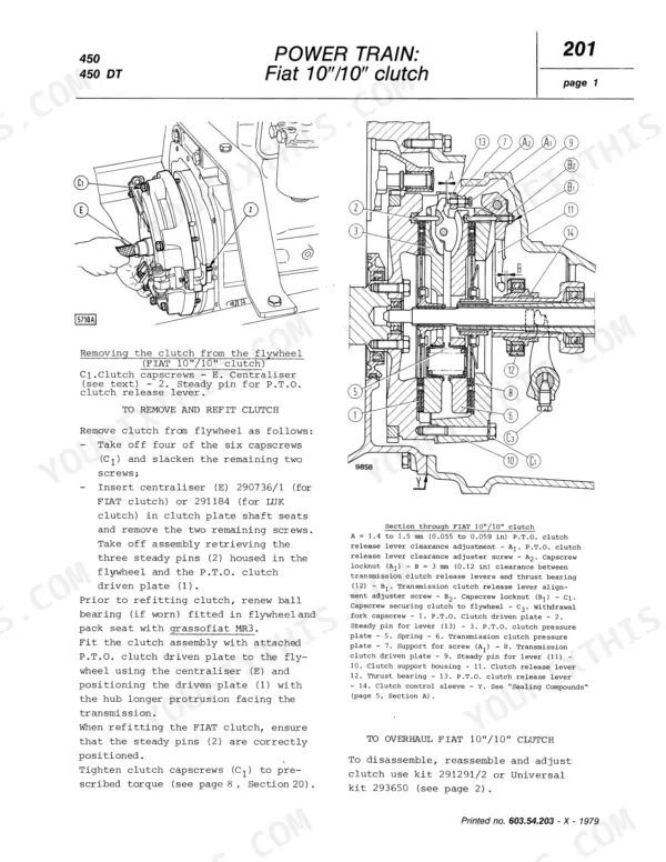
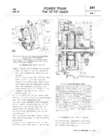
| Power Train | 33-68 | Clutch (to Remove and Refit Clutch, To Overhaul Fiat Clutch, To Adjust Fiat Clutch) |
| Front Axle - Steering | 69-82 | Front Axle (Sections, To Assemble - Disassemble - Inspect), Mechanical Steering (Steering Box Sections - to Disassemble - to Assemble, To Adjust Steering Box) |
| Live Front Axle | 83-94 | Front Axle (Sections Through U.T.B. Axle, To Adjust), Axle Drive - Drive Shaft (Axle Drive Sections - Drive Shaft) |
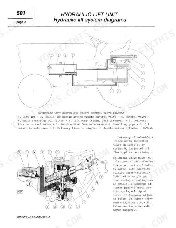
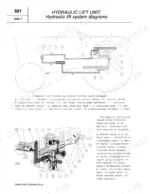
| Hydraulic Lift Unit | 95-114 | Lift (Description, Hydraulic Lift Diagrams, Control Linkage Schematics, To Disassemble - to Inspect - to Assemble, To Adjust, To Check Valves, Remote Control Valve) |
| Electrical System | 115-122 | Charging System, Diodes, Voltage Regulator, Alternator Warning Relay, Starter Motor, Battery, Fuses, Lighting |
| Service Tools | 123-126 | Engine Removal and Installation, Engine Block, Cylinder Head, Valve Gear, Crankgear, Fuel System, Cooling System, Clutch |
Quick Reference Specifications
| Specification | Value | Page |
|---|---|---|
| Capscrew, inlet tube end to axle case | 9 kgm (88 Nm, 65 ft.lb.) | p. 99 |
| Capscrew or stud nut, lift to axle case (C5) | 15.5 kgm (152 Nm, 112 ft.lb.) | p. 99 |
| Air cleaner oil change sediment depth | 1 cm or 1/2 inch | p. 9 |
| Driven plate thickness (450) | 9 mm | p. 34 |
| Driven plate thickness (450 Special) | 8.4 to 9.0 mm | p. 34 |
| Band lining thickness | 6 mm | p. 37 |
| Minimum wear thickness | 3.5 mm | p. 20 |
| Synchromesh spring camber | 1.5 mm (0.06 in) | p. 55 |
| Synchromesh spring test load | 1.4 to 1.55 kg (13.7 to 15.2 N, 3 to 3.5 lb.) | p. 55 |
| Piston working clearance in bore | 0.036 to 0.091 mm | p. 95 |
| Valve spool clearance in valve body | 0.025 to 0.035 mm | p. 96 |
| Commutator diameter | 41.5 to 42.0 mm (1.633 to 1.653 in) | p. 117 |
Fiat 450, 450 DT, 450 Special, 450 DT Special Common Problems This Manual Covers
Fiat 450 hydraulic lift unit relief valve cracks off with insufficient lifting power at the lift arms
Check the relief valve crack off setting before you tear the lift apart. Following page 95, it must open at 145 to 155 kg/cm² (142 to 152 bar, 2062 to 2205 psi), and the safety valve at 200 to 210 kg/cm² (196 to 206 bar, 2847 to 2989 psi). Reset whichever valve is off and get back to the field.
Manual Section: Hydraulic Lift Unit p. 95Hydraulic lift fails to hold load and lift arms show erratic movement under the implement
Inspect the lift piston and control valve during disassembly. Measure piston working clearance in the bore against 0.036 to 0.091 mm on page 95, then valve spool clearance in the valve body against 0.025 to 0.035 mm on page 96. Check the unload valve for leakage and torque its plug to 6.5 kgm (64 Nm, 47 ft.lb.) per page 99.
Manual Section: Hydraulic Lift Unit p. 95Clutch and transmission clutch linkage out of adjustment on the Fiat 10 inch or LUK 11 inch clutch
Verify which clutch your tractor carries first. The Fiat 10 inch and LUK 11 inch units each have their own on-bench, on-flywheel and linkage adjustment. Remove the clutch and measure driven plate thickness against your model's figure on page 34. Torque flywheel capscrews to 13.5 kgm (132 N·m, 98 Ft.lb.) on reassembly, per page 31.
Manual Section: Power Train p. 34Engine lubrication system oil pressure reads low at governed speed when checked with a test gauge
Test oil pressure with a master gauge at governed speed and compare against 3 to 4 kg/cm² (2.9 to 3.9 bar, 48 to 57 psi) from page 8. If it reads low, inspect the oil pump using the Engine section illustrations and lubrication system diagram. Torque main bearing cap capscrews to 15 kgm (147 N·m, 108.5 Ft.lb.) on reassembly.
Manual Section: Engine p. 8Starter motor commutator worn out of round with armature end float beyond limit
Remove the starter and measure commutator diameter against 41.5 to 42.0 mm (1.633 to 1.653 in) on page 117, with ovality no more than 0.05 mm (0.002 in). Check armature end float at 0.1 to 0.5 mm, then verify a solenoid plunger stroke of 10 mm and moving contact travel of 3.5 mm before you refit it.
Manual Section: Electrical System p. 117Front axle toe-in and camber out of spec with manual steering box worm and roller drive out of adjustment
Check front axle steering geometry, camber and toe-in following the Front Axle - Steering section starting on page 69, and adjust toe-in to spec. Adjust the steering box worm gear bearings first, then the worm and roller drive. On power steering tractors, test operating pressure and verify the relief valve crack off setting before blaming the box.
Manual Section: Front Axle - Steering p. 69Frequently Asked Questions
What is the torque specification for the cylinder head bolts on the Fiat 450?
The cylinder head hold-down screws must be tightened in three stages. The final torque for the third stage is 12 kgm (118 N·m, 87 ft.lb.). p. 18
What are the torque specifications for the Fiat 450 engine?
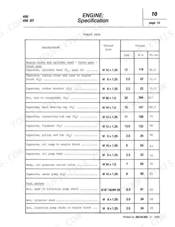
The engine tightening torque table lists each capscrew with its thread size and torque. For example, the cylinder head capscrews (C1) require 12 kgm (118 N·m, 86.8 ft.lb.), and the connecting rod cap capscrews (C6) require 11 kgm (108 N·m, 79 ft.lb.). p. 31
What is the correct valve clearance for the Fiat 450 engine?
The normal valve clearance for the engine is 0.25 mm (0.010 in) for the intake valves and 0.35 mm (0.014 in) for the exhaust valves. p. 8
What is the oil pressure for the Fiat 450 engine at governed speed?
The oil pressure at governed speed should be between 3 to 4 kg/cm² (2.9 to 3.9 bar, 48 to 57 psi). p. 8
What do I get after purchasing this Fiat 450 manual?
This is a 126-page searchable PDF ready for immediate download. Works on any device, so pull it up on your phone while you're under the hood. No shipping, no waiting.
Am I able to print pages from this Fiat 450 manual?
Yes. It prints from any PDF reader, so run off the pages you need for your own repair work.
Is the electrical system covered in this Fiat 450 Shop Manual?
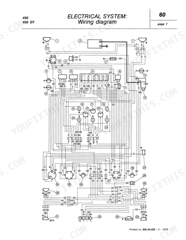
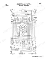
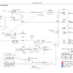
Yes. The electrical section covers the charging system, starter motor, battery and fuses, lighting, signals and switches, and includes a wiring diagram on page 121 plus a 12 V wiring diagram with a component index and cable colour code on page 122.
Reviews
There are no reviews yet.