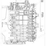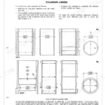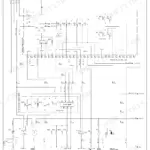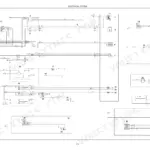
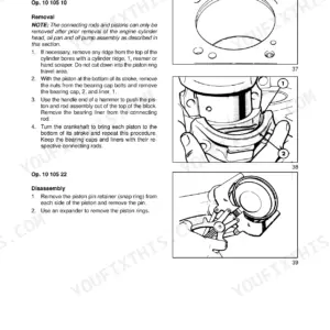
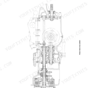
This 262-page Fiat 55-65, 60-65, 70-65, 80-65, 465C, 565C, 665C, 765C Workshop Manual PDF puts eight tractor and crawler models in one factory service book. You get complete wiring diagrams for Marelli, Lucas, and Bosch starters, hydraulic lift schematics with a troubleshooting chart, and injection pump calibration data for both Bosch VE and CAV DPS pumps. Open to the power train section for master clutch adjustments, steering clutch servicing, and torque data on everything from the engine down to the undercarriage and track frames. With the PTO turning 540 rpm, hold engine speed at 2200 rpm; that's the factory number for all eight models. Your machine is split in the shop and the clock is running. Bookmarked PDF, downloads in seconds, opens on any device; walk it out to the tractor and start wrenching.
Complete the set for your 55-65, 60-65, 70-65…
- Operator Manual: Fiat 70-65, 80-65 Crawler Operator Manual — Wiring Diagrams
Other edition of this manual
What's Inside This Fiat 55-65, 60-65, 70-65, 80-65 · 465C, 565C, 665C, 765C Manual
| System | Pages | Key Topics |
|---|---|---|
| Volume 1 - Fiat 55-65, 60-65, 70-65, 80-65: General | 5-10 | General Instructions, Shims, Rotary Shaft Seals, Floating Ring Seals, Sealing Compounds, Safety Precautions |
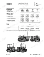
| Volume 1 - Specifications and Torque Data | 11-18 | Identification Data, Weights, Engine Specifications, Power Train and Undercarriage Data, Hydraulic and Electrical Data, Engine and Power Train Torque Values, Fastener Re-Use Checks (Cylinder Head, Main Bearing Cap, Connecting Rod Screws) |
| Volume 1 - Engine | 19-74 | Engine Block and Cylinder Head, Crank Gear, Valve Gear, Lubrication System, Cooling System, Fuel Injection System, Overhaul Limits |
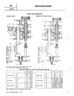
| Volume 1 - Power Train | 75-124 | Master Clutch, Transmission and Splitter, Reverser, Differential, Final Drives, PTO, Brakes |
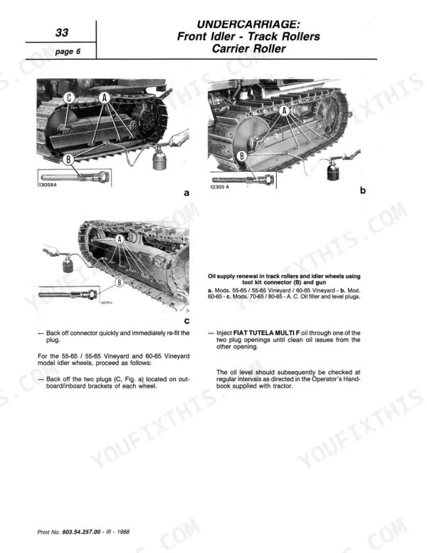
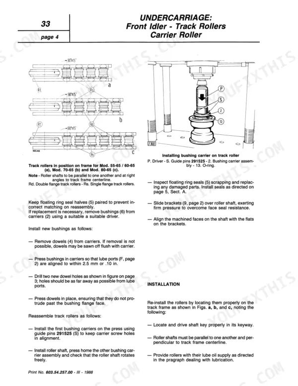
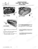
| Volume 1 - Undercarriage (Crawler Versions) | 125-142 | Track Chains, Track Tension Mechanism, Front Idler, Track and Carrier Rollers, Sprockets, Track Frame |
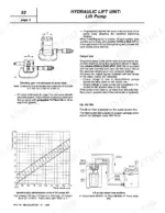
| Volume 1 - Hydraulic Lift Unit | 143-180 | Lift Cylinder, Control Valve, Lift Pump, Draft and Position Control, Remote Valves, Hydraulic Circuit Diagrams |
| Volume 1 - Electrical System | 181-196 | Charging System, Starter Motor, Battery, Fuses, Instruments and Controls, Wiring Diagrams |
| Volume 1 - Service Tools | 197-200 | Engine Tools, Crank Gear Tools, Fuel System Tools, Power Train and Hydraulic Tools |
| Volume 2 - Fiat 465C, 565C, 665C, 765C Crawlers: General | 201-206 | Foreword, Table of Contents, General Instructions, Safety Precautions |
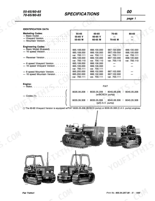
| Volume 2 - Specifications | 207-216 | Identification Data, Weights, Engine Specifications, Power Train, Undercarriage, Hydraulic and Electrical Data |
| Volume 2 - Engine | 217-248 | Engine Block, Crank Gear, Valve Gear, Cooling System, Lubrication System, Fuel System |
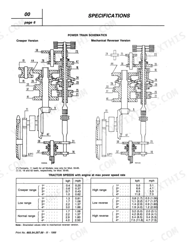
| Volume 2 - Power Train | 249-252 | Steering Clutches, Power Take-Off, Transmission, Splitter, Final Drives |
| Volume 2 - Hydraulic Lift Unit | 253-254 | Lift Specifications, Hydraulic Pump Specifications, Control Valve |
| Volume 2 - Electrical System | 255-258 | Controls and Instruments, Instrument Panel, Fuse Box, Charging and Starting Circuits, Wiring Diagrams |
| Volume 2 - Service Tools | 259-262 | Engine Tools, Power Train Tools, Undercarriage Tools |
Quick Reference Specifications
| Specification | Value | Page |
|---|---|---|
| Engine speed rate with PTO at 540 rpm | 2200 rpm | p. 249 |
Fiat 55-65, 60-65, 70-65, 80-65 · 465C, 565C, 665C, 765C Common Problems This Manual Covers
Fiat 55-65 engine loses power under load, bogs down with black exhaust smoke at full throttle
Check the injection pump calibration first; sediment in aged fuel systems throws off delivery. Verify the engine reaches 2200 rpm with the PTO turning 540 rpm, the speed spec listed on page 249. If revs fall away under load, pull the injectors, test spray pattern, and recalibrate pump delivery on a test bench.
Manual Section: Fuel System Injection Pump CalibrationHydraulic lift loses pressure after 10 to 15 minutes, boom drops or lifts slowly when hot
Test lift pressure against the diagnostic values on page 170 with fluid at operating temperature. Pressure that fades after 10 to 15 minutes of running points to a worn pump or air admission through a suction leak. Inspect cylinder seals for weeping, then trace the circuit on the hydraulic schematic to isolate internal leakage.
Manual Section: Hydraulic Lift Unit p. 170Clutch slips under load, pedal feels loose, gears grind or refuse to engage
Adjust the master clutch linkage before condemning the disc; a loose pedal usually means free play has drifted out of adjustment. Set the control lever per the adjustment procedure, then confirm the PTO clutch engages cleanly with the shaft turning 540 rpm. If slippage continues after adjustment, split the tractor and inspect the disc for glazing.
Manual Section: Power Train Clutch AdjustmentsBlue exhaust smoke at working speed, engine burns oil between service intervals
Run a compression test on all cylinders with the engine warm; low, even readings across the board mean worn rings rather than one bad valve. Check smoke color with the engine at 2200 rpm, the speed that drives the PTO at 540 rpm: blue means oil past the rings, black means overfueling. Compare cylinders against each other before ordering parts.
Manual Section: Engine Compression TestFrequently Asked Questions
What are the recommended service intervals?
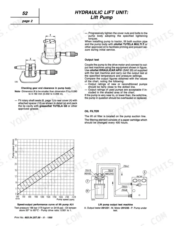
The manual recommends replacing the oil filter cartridge every 400 working hours. For the cooling system, the coolant is effective for a period of 2 years or 1500 hours, after which the system should be drained, flushed, and refilled. p. 16
What fluids and capacities does this machine require?
The machine requires various fluids, including engine oil (Sump oil) with a capacity of 7.5 liters (1.98 US Gallons) for 55-65 models, and coolant (Water and FIAT "PARAFLU 11") with a capacity of 10.5 liters (2.77 US Gallons). The power train (transmission, bevel drive) requires 7.1 liters (1.87 US Gallons) of oil. p. 18
What are the valve clearance specifications?
The valve clearance specifications are 0.45 mm (0.0177 in) for intake and 0.35 mm (0.0138 in) for exhaust when checking timing. For normal (cold or warm) operation, the intake valve clearance is 0.25 mm (0.0100 in) and the exhaust is 0.35 mm (0.0138 in). p. 17
What torque specifications are listed?
The manual lists various torque specifications. For cylinder head screws, the pre-torque is 60 Nm (6.1 kg-m or 44 ft-lb) followed by an angle of 90° + 90°. Main bearing cap screws require 80 Nm (8.2 kg-m or 59 ft-lb) and an additional 90° angle. Connecting rod cap screws are tightened to 40 Nm (4.1 kg-m or 29 ft-lb) with a 60° angle. p. 19
What is the specified tightening torque for the cylinder head bolts?
For all models, the cylinder head bolts are tightened in successive stages. The initial torque is 60 Nm (6.1 kgm or 44 ft lb), followed by a second stage of 60 Nm (6.1 kgm or 44 ft lb), and then two angular tightening stages of 90° each. p. 12
How quickly can I access this manual after buying?
You get a 262-page scanned PDF that downloads instantly after checkout. Open it on your laptop, tablet, or phone, and bring it right to the shop floor.
Are there any print restrictions on this manual?
Yes. The PDF has no DRM restrictions, so print any page or section you need for your shop. Works with any standard printer.