
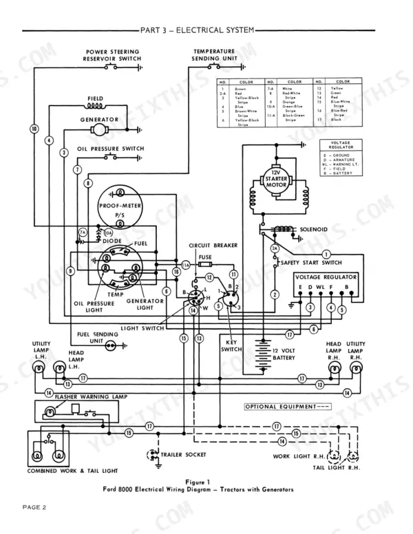
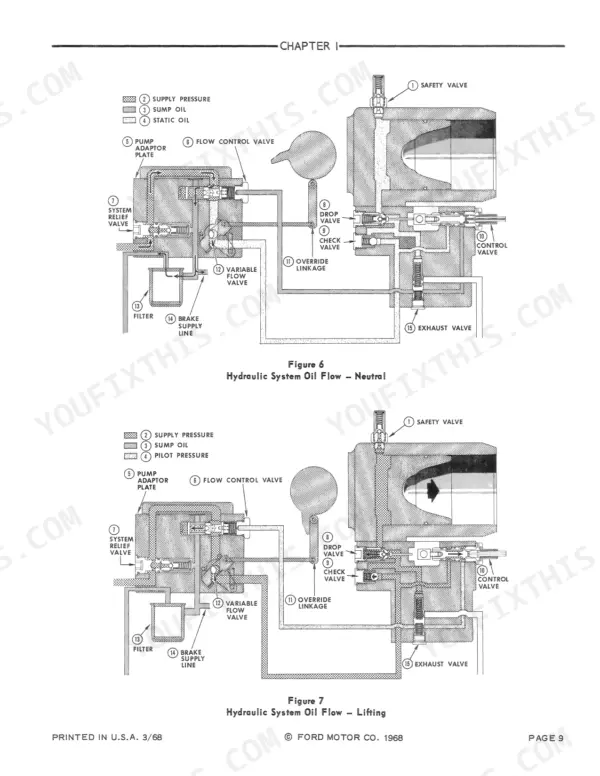
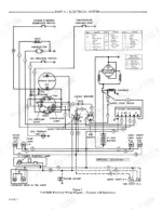

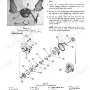
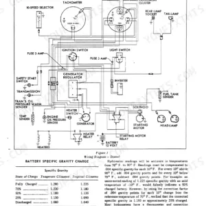
Every one of the 452 pages in this Ford 8000 Service Manual PDF (OEM #40800020) covers the 8000, 9000, 8600, and 9600 tractors, from cylinder head to rear axle. You get factory wiring diagrams for the charging and starting circuits, hydraulic schematics for the lift cover and remote valves, and exploded views of the transmission, differential, and turbocharger. A full troubleshooting section and torque tables back up step-by-step procedures, right down to splitting the tractor for engine or axle removal. Check PTO system pressure at 135-165 psi before you condemn the pump; the specs section lists it in black and white. Forum threads won't rebuild your hydraulic lift. This bookmarked PDF opens on any device; load it on a tablet, walk out to the tractor, and start wrenching.
Other edition of this manual
What's Inside This Ford 8000, 9000, 8600, 9600 Manual
| System | Pages | Key Topics |
|---|---|---|
| Engine and Lubrication System | 3-74 | Cylinder Head, Valves, Timing Gears, Oil Pump, Turbocharger, Cooling System |
| Fuel System | 75-100 | Fuel Tank, Fuel Lines, Fuel Filters, Fuel Lift Pump, Fuel Injection Pump, Injectors |
| Electrical System | 101-146 | Lights, Switches, Instrument Panel, Alternator, Voltage Regulator, Starter Motor |
| Transmission and Clutch | 147-220 | Transmission, Parking Brake, Planetary Gear Set, Clutch, Control Valve, Gear Shift Linkage |
| Rear Axle, Brakes, and Power Take-Off | 221-268 | Rear Axle, Brakes, Power Take-Off, Differential, Drive Pinion, Brake Master Cylinder |
| Hydraulic System | 269-308 | Hydraulic Lift Cover, Lift Cylinder, Control Valve, Torsion Bar Linkage, Hydraulic Pump, Remote Control Valves |
| Steering System, Front Axle, Wheels and Tires | 309-392 | Steering System, Front Axle, Wheels, Tires, Hydrostatic Steering Motor, Front Pedestal |
| Separating the Tractor | 393-414 | Engine Removal, Transmission Removal, Rear Axle Assembly Removal, Front Axle Assembly Removal |
| Tractor Maintenance Schedule | 415-422 | Pre-Delivery Service, 50-Hour Service, Lubrication Chart, Maintenance Intervals, Seasonal Service |
| Air Conditioning and Heating | 423-452 | Compressor Clutch, Expansion Valve, Condenser Fan, Evaporator Core, Heater Control Valve, Heater Core |
Quick Reference Specifications
| Specification | Value | Page |
|---|---|---|
| All Models | ||
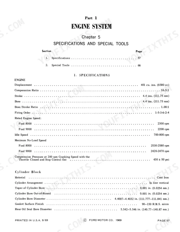
| Engine Displacement | 401 cu. in. (6580 cc) | p. 61 |
| Compression Ratio | 16.5:1 | p. 61 |
| Firing Order | 1-5-3-6-2-4 | p. 61 |
| Compression Pressure at 200 rpm Cranking | 430 ± 50 psi | p. 61 |
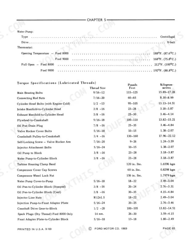
| Main Bearing Bolts Torque (9/16-12) | 115-125 lb-ft (15.89-17.28 kgm) | p. 69 |
| Cylinder Head Bolts Torque, engine cold (1/2-13) | 95-105 lb-ft (13.13-14.51 kgm) | p. 69 |
| Connecting Rod Nuts Torque (7/16-20) | 60-65 lb-ft (8.30-8.99 kgm) | p. 69 |
| P.T.O. System Pressure | 135-165 psi | p. 261 |
| Ford 8000 | ||
| Rated Engine Speed (Ford 8000) | 2300 rpm | p. 61 |
| Thermostat Opening Temperature (Ford 8000) | 188°F (87.6°C) | p. 69 |
| Ford 9000 | ||
| Rated Engine Speed (Ford 9000) | 2200 rpm | p. 61 |
| Thermostat Opening Temperature (Ford 9000) | 168°F (75.6°C) | p. 69 |
Ford 8000, 9000, 8600, 9600 Common Problems This Manual Covers
Ford 9600 dual power slips under load in high range but holds in low range
Check dual power system pressure using the transmission troubleshooting procedure in the section starting on page 147. The same charge pump feeds the PTO circuit, so verify P.T.O. system pressure holds 135-165 psi, the spec on page 261. Good pressure with high-range slip means an internal leak or burned direct clutch pack; plan on splitting the tractor.
Manual Section: Transmission and Clutch p. 147PTO engages at idle but slips or stalls the implement under load
Test P.T.O. system pressure before splitting anything; it must hold 135-165 psi per the spec on page 261. Pressure in range with continued slip points to a worn PTO clutch pack. Low pressure means the shared charge pump or an internal leak, so work through the rear axle and PTO troubleshooting steps starting on page 221.
Manual Section: Rear Axle, Brakes, and Power Take-Off p. 261Power steering jerky or erratic, front wheels surge and won't hold position when turning
Inspect the Hydramotor for external leakage, then check reservoir oil level and condition against the 50-hour service chart on page 415. Jerky or surging wheels usually mean worn ring, rotor, or vane parts inside the steering motor; steering in one direction only points to a sticking control valve spool. Follow the steering troubleshooting procedures starting on page 309.
Manual Section: Steering System, Front Axle, Wheels and Tires p. 309Hydraulic lift slow to raise, three-point hitch drifts down, pump noisy under load
Drain a hydraulic oil sample and look for contamination before condemning the pump; dirty oil wrecks the relief valve seat and pump chambers. Change oil and filters at the 50-hour interval in the maintenance schedule on page 415, then run the troubleshooting checks for slow lift and drift-down starting on page 269.
Manual Section: Hydraulic System p. 269Frequently Asked Questions
How do I test the PTO system pressure on a Ford 9600?
To test the PTO system pressure, tap into the 1/4 inch pipe plug opening in the hydraulic pump cover using the N-774-B Select-O-Speed Gauge Kit. With the engine at 700 rpm and the PTO lever in the START position, the gauge should register 135-165 psi. p. 228
What is the torque specification for the cylinder head bolts on the Ford 8000/9000 engine?
The cylinder head bolts should be tightened in the specified sequence in three progressive steps, reaching a final torque of 100 lbs. ft. (13.8 m.k.g.). p. 15
What is the correct engine oil capacity for a Ford 8600 tractor?
The engine oil capacity for a Ford 8600 is 10 quarts (9.4 liters) for a standard refill, or 12 quarts (11.4 liters) when replacing the main element. p. 74
How do I adjust the clutch pedal free travel on a Ford 8000?
The clutch pedal free travel must be maintained at 9/16 inch to 5/8 inch as measured between the pedal stop and the pedal shank. Adjustment is made by disconnecting the clevis from the clutch release lever and turning the rod. p. 187
What is the specified pressure setting for the hydraulic system relief valve?
The hydraulic system relief valve is set to 2450-2550 psi. If the pressure is not within this range, it must be adjusted by adding or removing shims. p. 273
Will this Ford 8000 Service Manual download right away?
You get a 452-page scanned PDF that downloads instantly after checkout. Open it on your laptop, tablet, or phone, and bring it right to the shop floor.
Are there any print restrictions on this Ford 8000 manual?
Printing is allowed without restriction. Pull the pages you need for the job and bin them when they get greasy.


![Ford 2610 parts catalogue figure 15A08[C], seat belt for the two-post ROPS in the US market, with its part table](https://youfixthis.com/wp-content/uploads/2026/08/ford-2610-tractor-parts-manual-cab-780-64x83.webp)
Reviews
There are no reviews yet.