
A loader that pays for itself by the bucketload can't sit idle over a missing spec, and the 712 pages of this Ford A-62, A-64, A-66 service manual PDF (OEM 40006230A) exist so yours never has to. Wiring diagrams trace every circuit from the battery through the lights, switches, instruments and starting system, and hydraulic schematics map oil flow through the loader valve, bucket cylinders and lift arms. Troubleshooting charts walk the engine, fuel system and turbocharger from symptom to cause, backed by exploded views for the overhauls on the cylinder head, axles and Allison powershift transmission. Hold your converter stall test under 30 seconds, and pull the turbocharger down to the exhaust manifold at 30 to 35 pounds-feet. Every hour spent hunting a figure is an hour the machine sits parked. Bookmarked and text-searchable, this PDF is bought once and yours for as long as you run the loader.
What's Inside This Ford A-62, A-64, A-66 Manual
| System | Pages | Key Topics |
|---|---|---|
| Service Manual | 1 | Engine System, Fuel System, Electrical System, Transmission, Engine-Transmission Removal, Axles, Brakes, Drive Shafts |
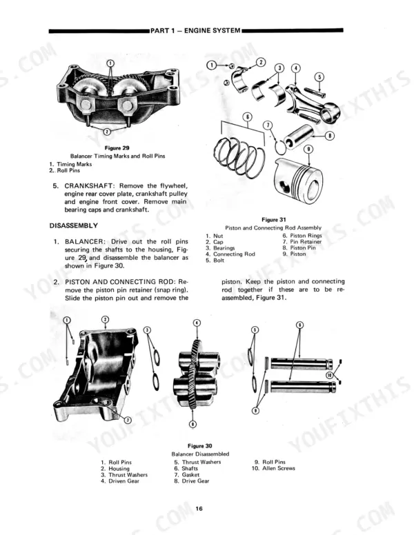
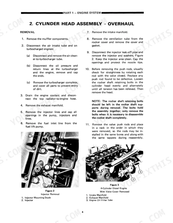
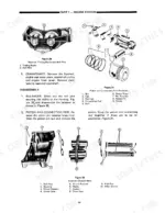
| Engine System | 5-62 | Engine, Cylinder Head Assembly, Timing Gears, Camshaft, Oil Pump, Balancer, Connecting Rod and Piston, Crankshaft |
| Fuel System | 63-106 | Fuel Tank Lift Pump Filter and Fuel Lines, Trouble Shooting Specifications and Special Tools |
| Electrical System | 107-190 | Wiring Circuit Protection Lights Switches Instruments and Miscellaneous Electrical Equipment, Starting System |
| Transmission | 191-284 | Servicing the Transmission |
| Engine Transmission Removal | 285-304 | Description and Operation, Cylinder Head Assembly - Overhaul, Timing Gears, Camshaft and Oil Pump - Overhaul, Balancer, Connecting Rod and Piston, Bearings |
| Axles Brakes Drive Shafts Wheels and Tires | 305-380 | Description and Operation |
| Steering | 381-416 | Description and Operation, Cylinder Relief Valve Assembly Removal Installation and Overhaul |
| Hydraulic System | 417-480 | Description and Operation, Component Installation |
| Ford Wheel Loader Frames Loader Linkage and Buckets | 481-502 | Description and Operations, Component Assembly |
| Operator's Platform and Sheet Metal | 503-514 | Operator's Platform, Hood, Side Panels, Noise Insulating Panel, Radiator Shell, Steering Motor, Transmission Controls |
| Air Conditioning and Heating | 515-544 | Compressor, Condenser Core, Dehydrator-Receiver, Evaporator Core, Expansion Valve, Heater Core, Defroster-Fan Filter Assembly |
| Reference Information | 545-712 | Allison Powershift Transmissions, Model Code Designation, Transmission Torque Converter, Power Reversing Transmission, Hydraulic System, Loader Linkage, Bucket Level Indicator |
Quick Reference Specifications
| Specification | Value | Page |
|---|---|---|
| All Models | ||
| Radiator hose rod diameter | 0.1875 in. (4.76 mm) | p. 32 |
| Water pump impeller shaft internal diameter | 0.75 in. (19 mm) | p. 60 |
| Turbocharger-to-Exhaust Manifold Torque | 30-35 Pounds/Feet | p. 55 |
| Fuel Injection Pump to Front Plate | 20-25 Pounds Feet | p. 104 |
| Stall test maximum duration | 30 seconds | p. 215 |
| Stall test converter-out temperature limit | 250°F (122°C) | p. 216 |
| Maximum warp of disc (A-62 F&R, A-64 R) | 0.004 in. | p. 373 |
| Maximum warp of disc (A-64 R, A-66 F&R) | 0.003 in. | p. 373 |
| A-62 | ||
| Engine Oil Capacity (4-Cylinder) | 19 quarts | p. 60 |
| Hydraulic Pump Capacity (A-62) | 13 gpm @ 2100 rpm | p. 477 |
| A-64, A-66 | ||
| Engine Oil Capacity (6-Cylinder) | 26 quarts | p. 60 |
| A-64 | ||
| Hydraulic Pump Capacity (A-64) | 14 gpm @ 2300 rpm | p. 477 |
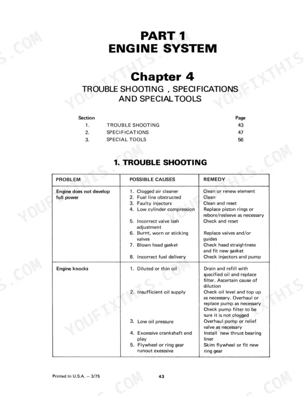
Ford A-62, A-64, A-66 Common Problems This Manual Covers
Ford A-64 loader brakes weak or failing completely, pedal travels but machine barely stops
Check the brake fluid for milky discoloration; water intrusion ruins the internal discs. Test the pressure relief valve, which must hold 1050-1150 psi on all three models. Pull the wheels and measure disc warp against the limits on page 373, then replace any disc showing water etching or heat checking.
Manual Section: Axles Brakes Drive Shafts Wheels and Tires p. 373Loader feels gutless once warmed up, loses power pushing into the pile, normal when cold
Run a stall test before condemning the engine. Bring converter-out oil to at least 225°F (107°C), hold each stall no longer than 30 seconds, and never let converter-out temperature pass 250°F (122°C) per page 216. Low stall speed with a healthy engine points to converter slip; check main clutch pressure while you are in there.
Manual Section: Transmission p. 216Engine cranks but will not start after air filter or fuel filter service
Pull the outer air filter element and check it for moisture; the engine will not start with a wet element installed. Fit a dry element, then bleed the fuel system at the filters. If the injection pump was disturbed, torque the pump-to-front-plate nuts to 20-25 lb-ft as listed on page 104.
Manual Section: Fuel System p. 104Engine runs hot under load, temperature gauge climbs, coolant pushing out the overflow
Check both radiator hoses for soft spots and internal collapse under suction; aged hoses are a known failure on these machines. Verify the hose support rod measures 0.1875 in. (4.76 mm) per the spec on page 32, then work the overheating chart starting before pulling the water pump.
Manual Section: Engine System p. 32Black smoke under load, turbocharger whine, noticeable power loss at full throttle
Inspect the air filter and intake tract first; a restricted element mimics turbo failure. Check the turbine shaft for play and oil in the compressor housing. Reinstall or replace the unit and torque the turbocharger-to-exhaust-manifold nuts to 30-35 lb-ft using the values on page 55, then verify boost under load.
Manual Section: Engine System p. 55Frequently Asked Questions
What is the torque specification for the cylinder head bolts on the Ford A-62, A-64, and A-66 engines?
The cylinder head bolts for the 4- and 6-cylinder engines should be tightened in three progressive steps. The final torque value is 110 lb. ft. (15.21 kgm). p. 15
What is the correct valve lash clearance for the exhaust valves on the Ford A-62, A-64, and A-66 engines?
The specified lash clearance for the exhaust valves is 0.017 to 0.019 inches (0.43 to 0.48 mm). p. 54
What is the oil capacity for the 4-cylinder engine used in the Ford wheel loaders?
The oil capacity for the 4-cylinder engine, including the oil in the filter, is 19 quarts (17.9 liters). p. 60
What is the correct fan belt deflection for the cooling system?
The fan belt should have a deflection of 0.5 to 0.75 inches (12 to 18 mm) when measured midway between the pulleys. p. 60
What is the pressure relief valve setting for the power brake pump on a Ford A-62, A-64, A-66?
The pressure relief valve for the power brake pump is set at 1050-1150 psi (72-79 bar). p. 373
How quickly can I access this Ford A-62 manual after buying?
A single searchable PDF file of 712 pages, downloadable right after payment. Nothing ships, nothing waits in the mail.
Am I able to print pages from this Ford A-62 manual?
Yes. Print a single page or a chapter for your own shop use, on letter or A4.


Reviews
There are no reviews yet.