
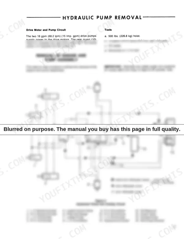
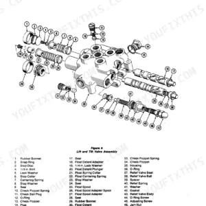
Factory pressure settings, pump teardown sequences, and control valve tolerances for the CL-20 compact loader survive in one document: this 48-page Ford CL-20 repair manual PDF, OEM ID 40002010. Hydraulic coverage runs from pump removal through pressure tests, with schematics tracing the implement pump and cooling circuit, while both the gear and piston pumps get full disassembly, inspection, and reassembly sequences. Exploded views break the cylinders and control valves down part by part, the wiring diagram maps the alternator, starter, and solenoid, and the troubleshooting section sorts a noisy pump from foaming oil and shaft seal leakage. Check your implement pump and cooling circuit at 1500 ± 50 PSI, then tighten the axle bearing mount bolts to 30 lbs. ft. (4.15 kgm). A rebuilt pump sits on the bench until you find its relief setting. Bookmarks and a live text layer put that page two clicks from the cover.
What's Inside This Ford CL-20 Repair Manual
| System | Pages | Key Topics |
|---|---|---|
| Hour Inspection | 4-5 | Engine, Fuel System, Electrical, Air Cleaner, Hydraulic System, Drive System |
| Safety Precautions | 6-7 | Seat Belt, Engine Operation, Lift Arms, Bucket, Parking, Refueling |
| Description and Operation | 8 | Drive System, Steering, Frame Assembly, Hydraulic System, Implement Pump, Cooling Circuit |
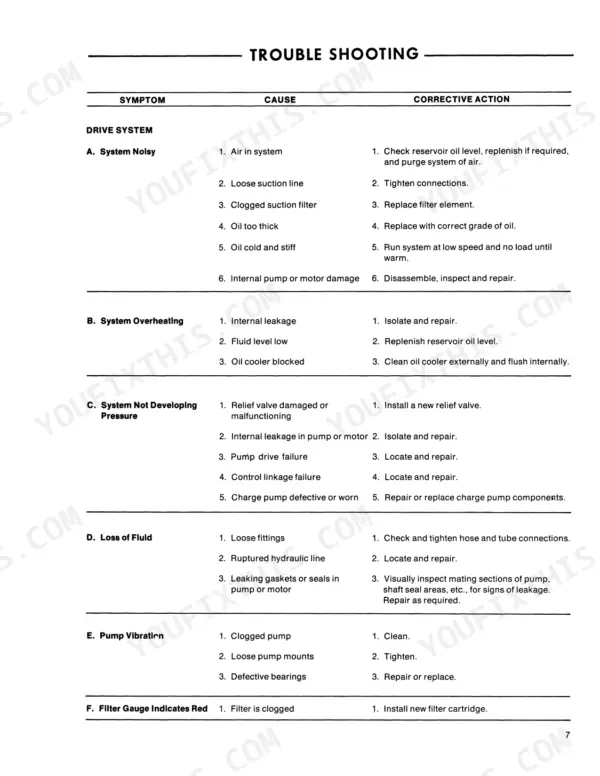
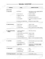
| Trouble Shooting | 9 | Engine, Electrical, Drive System, Loader System |
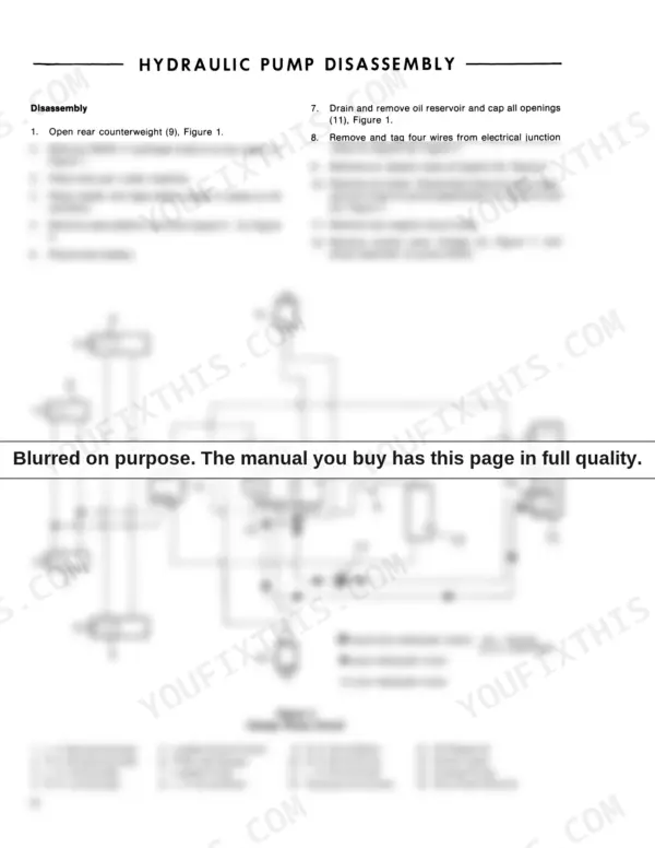
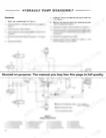
| Hydraulic System | 10-17 | Pump Removal, Pump Disassembly, Pump Assembly, Pressure Tests |
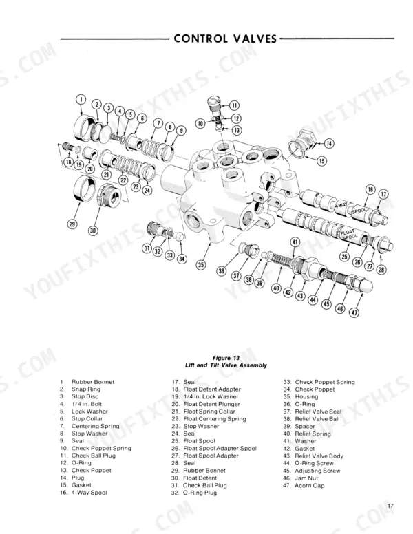
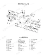
| Control Valves | 18-19 | Valve Removal, Disassembly, Inspection, Assembly, Seal Replacement |
| Cylinders | 20-22 | Removal, Disassembly, Inspection, Repair, Assembly, Installation |
| Power Train | 23 | Noisy Pump, Oil Heating, Shaft Seal Leakage, Foaming Oil, Gear Pump Assembly |
| Gear Pump | 24-25 | Gear Assembly, Front Plates, Back Plates, Body, Reassembly |
| Piston Pump | 26-30 | Charge Pump, Relief Valve, Piston Block, Cam Plate, Drive Shaft, Gerotor Gear |
| Lubrication and Maintenance | 31-39 | Lubrication Chart, Adjustments |
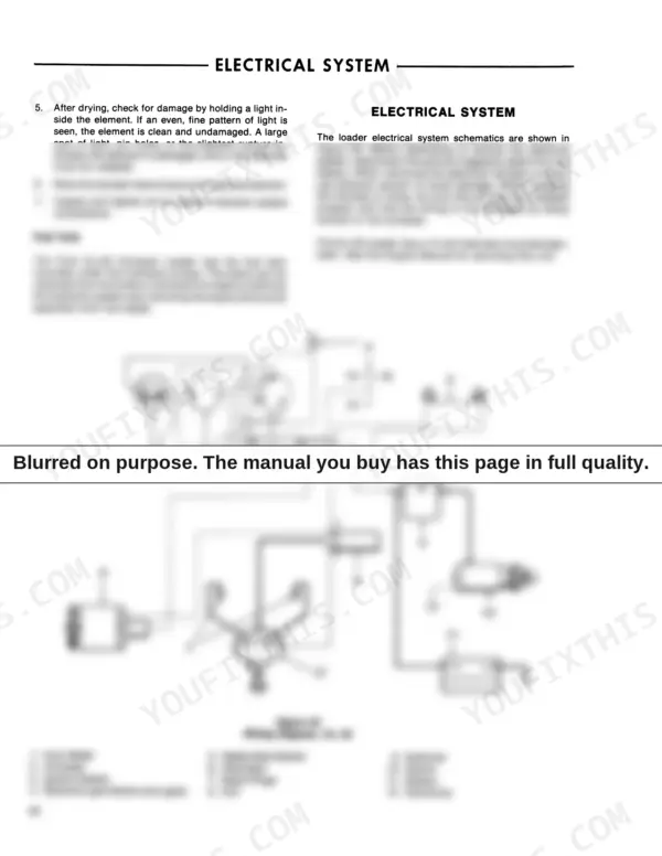
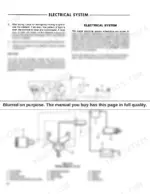
| Electrical System | 40 | Alternator, Battery, Ignition Switch, Starter, Solenoid, Wiring Harness |
| Specifications | 41-48 | Performance, Engine, Loader, Electrical, Drive System, Hydraulic System |
Quick Reference Specifications
| Specification | Value | Page |
|---|---|---|
| Axle bearing mount bolts torque | 30 lbs. ft. (4.15 kgm) | p. 4 |
| Hydraulic pressure in drive system at pump | 2000 psi (137.8 bar) | p. 5 |
| Pressure check (Implement Pump and Cooling Circuit) | 1500 ± 50 PSI (103.41 ± 3.45 BAR) | p. 11 |
| Bolt torque for spool | 10 lbs. ft. | p. 18 |
| Battery | 12 volt, 40 Amp. hrs. | p. 41 |
| Engine Idle Speed | 900 rpm | p. 5 |
| Governor Speed | 3600 rpm | p. 5 |
| Drive System Hydraulic Pressure | 2000 psi | p. 5 |
| Axle Bearing Mount Bolt Torque | 30 lbs. ft. | p. 4 |
| Drive System Charge Pump Pressure | 60-100 psi | p. 16 |
| Piston Packing Lock Nut Torque | 150-175 lbs. ft. | p. 22 |
| Collar Nut Torque | 125-150 lbs. ft. | p. 22 |
Ford CL-20 Common Problems This Manual Covers
Ford CL-20 engine cranks but will not start, or fires briefly then stalls right away
Check battery voltage and cable connections first; the machine runs a 12 volt, 40 amp hour battery, listed in the electrical specs on page 41. Test the starter solenoid, plugs, and ignition wires using the electrical troubleshooting steps on pages 8 and 9. Drain stale fuel and clean the carburetor before condemning any parts.
Manual Section: Electrical System Troubleshooting p. 8Loader hydraulics weak or dead after an engine swap, lift arms barely move under load
Verify pump coupling alignment at the engine adapter before chasing valves. Tee a gauge into the loader circuit and run the pressure test on page 15; you want 1550 ± 50 psi (106.7 ± 3.4 bar) at relief. Low readings point to the implement pump; removal and rebuild steps start on page 10.
Manual Section: Hydraulic System p. 15Drive system noisy and sluggish, loader creeps or will not move at full throttle
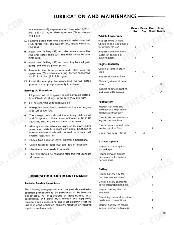
Check charge pump pressure first; it must hold 60 to 100 psi (4.13 to 6.89 bar) for the drive to work, per the test on page 16. Confirm drive pressure reaches 2000 ± 50 psi at full stroke. If both read low, tear into the piston pump starting on page 26 and inspect the charge relief valve.
Manual Section: Piston Pump p. 26Lift arms drift down with a loaded bucket, cylinders leak oil past the rod seals
Test whether the valve or a cylinder is bypassing using the drift procedure on page 10. If a cylinder leaks internally, pull it, replace the piston packing and rod seals following the steps that start on page 20, then torque the piston packing lock nut to 150-175 lbs. ft. (20.74-24.20 kgm).
Manual Section: Cylinders p. 20Engine surges or dies after the machine sits all winter, carburetor floods or starves
Drain the tank and fuel lines, then clean the carburetor jets and float bowl before touching anything else. Refill with fresh fuel, set idle to 900 rpm and governed speed to 3600 rpm per the settings on page 5, and run through the hour inspection items on page 4 to catch a plugged air cleaner or fuel screen.
Manual Section: Hour Inspection p. 4Frequently Asked Questions
What are the torque specifications for the axle bearing mount bolts on a Ford CL-20?
The axle bearing mount bolts should be tightened to 30 lbs. ft. (4.15 kgm). p. 4
What is the hydraulic pressure specification for the drive system at the pump on a Ford CL-20?
The hydraulic pressure in the drive system at the pump should be 2000 psi (137.8 bar) at 3600 engine rpm. p. 5
What is the torque specification for the piston packing lock nut on a Ford CL-20?
The piston packing lock nut should be torqued to 150 - 175 lbs. ft. (20.74 - 24.20 kgm). p. 22
What is the required torque for the gear pump assembly bolts on the Ford CL-20?
The bolts for the gear pump assembly should be drawn up evenly to 23 ft. lbs. (3.18 kgm) torque. p. 26
What is the hydraulic oil reservoir capacity for the Ford CL-20?
The loader hydraulic oil reservoir capacity is approximately 7 U.S. gallons (26.5 Liters) (5.83 Imperial gallons). p. 35
Is this Ford CL-20 manual a download or a disc?
One searchable PDF covering 48 pages, delivered instantly. No disc, no shipping, no waiting on the post.
Can I print pages of this Ford CL-20 manual for my own shop?
Yes. Many buyers print one chapter at a time for their own shop and keep the rest on a tablet.


Reviews
There are no reviews yet.