When a CL-30 loses lift halfway through a pile, or a CL-40's drive chain starts slapping the case, the fix starts with this Ford CL-30, CL-40 repair manual PDF: 32 pages of factory service data filed under OEM ID 40003020. Hydraulic schematics trace the tandem pump circuit through the loader control valve, bucket and lift cylinders, and the backpressure valve, while wiring diagrams map the electrical system beside them. Pressure test procedures walk you through installing a hydraulic tester and checking pump performance before you condemn a part. Set the loader relief at 1550 ± 50 psi, verify 65 ± 5 psi of backpressure, and torque the drive pump retaining screws to 42-45 lbs. ft. on reassembly. A parked loader is billable hours draining away. Download the bookmarked, text-searchable PDF, print the pages you need, and let them get greasy on the bench.
What's Inside This Repair Manual
| System | Pages | Key Topics |
|---|
| Description and Operation | 5-6 | Drive System, Hydraulic Motors, Chain Drive, Steering Linkage, Frame Assembly |
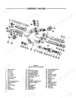
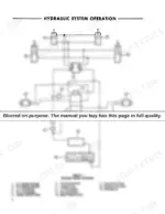
| Hydraulic System Operation | 7-8 | Tandem Pump, Loader Control Valve, Bucket Cylinders, Lift Cylinders, Backpressure Valve, Hydraulic Oil Cooler |
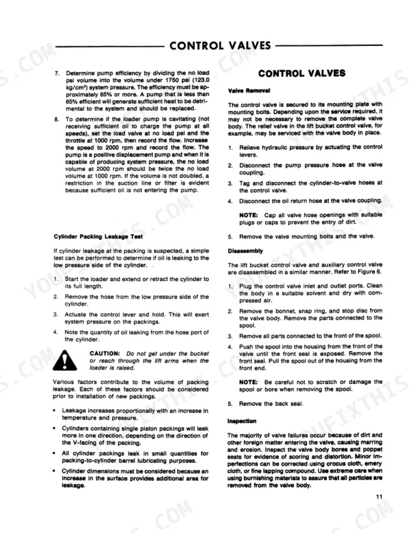
| Pressure Tests and Adjustments | 9-10 | Drive System Pressure Test, Hydraulic Pump Performance Test, Installing the Hydraulic Tester, Pump Performance Test Procedure, Cylinder Packing Leakage Test |
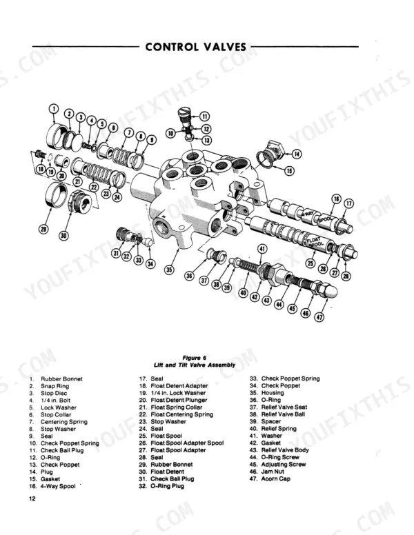
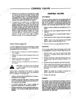
| Valve Removal | 11-13 | Disassembly, Inspection, Assembly and Seal Replacement, Installation |
| Cylinders | 14-15 | Removal, Disassembly, Repair, Assembly, Installation |
| Loader Pump | 16 | Disassembly, Repair |
| Drive Pump | 17-18 | Disassembly, Repair, Assembly |
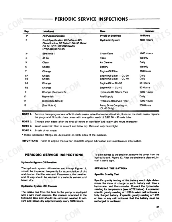
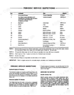
| Lubrication and Maintenance | 19-26 | Lubrication Chart, Periodic Service Inspections, Servicing the Battery, Drive Chain Adjustment, Drive Control Lever Adjustment, Servicing the Air Cleaner, Fuel Tanks |
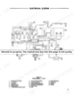
| Specifications | 27-32 | Engine Performance, Loader Controls, Electrical System, Drive System, Hydraulic Pump, Tire Inflation Pressures |
Quick Reference Specifications
| Specification | Value | Page |
|---|
| Drive pump retaining screw torque | 42 - 45 lbs. ft. (5.81 - 6.22 kgm) | p. 19 |
| Loader system relief pressure | 1550 ± 50 psi (109.0 ± 3.5 kg/cm²) | p. 9 |
| Backhoe installation system relief pressure | 2000 ± 50 psi (140.6 ± 3.5 kg/cm²) | p. 9 |
| Drive System Pressure | 2500 psi | p. 9 |
| Hydraulic System Oil Capacity | 14 gallons | p. 30 |
| Piston Packing Lock Nut Torque | 150-175 lbs. ft. | p. 16 |
| Collar Nut Torque | 125-150 lbs. ft. | p. 16 |
| Loader Pump Capacity | 16 gpm | p. 30 |
| Operating Weight | 4145 pounds | p. 29 |
| Lift Capacity | 1500 pounds | p. 29 |
| Tire Inflation Pressure (Standard) | 45 psi | p. 30 |