
On an LGT 12H the safety interlock switch list and the wiring diagrams are both in this book. Ford published it as 238242 for the LGT 12H and LGT 17H garden tractors, model numbers 09GN2205 and 09GN2206, 56 pages in all.
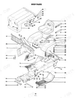
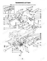
It runs from battery prep and steering wheel assembly through the controls, the trial run and the interlock system, then into the work that keeps the tractor alive: brake cable and pad adjustment, electric clutch adjustment, hydrostatic drive adjustment, grease fittings and the transmission oil filter. Pages 28 to 51 are component parts lists, broken out by body, transmission and lift, steering, brake, wheels, engine and electrical.
Complete the set for your LGT 12H, LGT 17H, LGT 09GN2205…
- Repair Manual: Ford LGT12–LGT18H Service Manual — Wiring Diagrams
Other edition of this manual
- Ford LGT 17H, 09GN2204 Operator Manual Original price was: $31.99.$19.99Current price is: $19.99.
What's Inside This Ford LGT 12H, LGT 17H, LGT 09GN2205, LGT 09GN2206 Operator Manual
| System | Pages | Key Topics |
|---|---|---|
| Introduction | 3-7 | Authorized Parts and Service Dealer, Engine Instructions, Operator Safety, Tractor Side Identification, Model and Serial Number Identification, The Tractor, Safety Precautions |
| Preparing Tractor for Operation | 9-10 | Battery Preparation, Battery Installation, Steering Wheel Assembly, Seat Attachment, Seat Adjustment |
| Initial Servicing | 11-12 | Crankcase Oil, Fuel Tank Filling, Tire Pressure, Lubrication Points |
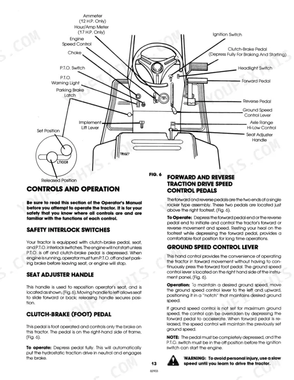
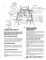
| Controls and Operation | 13-15 | Seat Adjuster Handle, Clutch-Brake Pedal, Traction Drive Speed Control Pedals, Ground Speed Control Lever, Engine Speed Control, Choke Control, Parking Brake Latch, P.T.O. Switch |
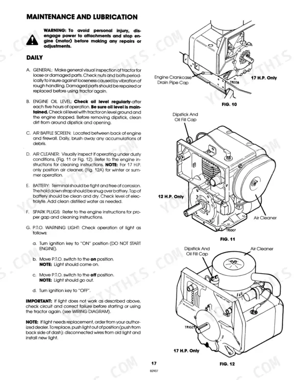
| Trial Run | 16-18 | Interlock System, Starting Procedure, Operating Procedure, Stopping Procedure, Engine Oil Level, Air Baffle Screen, Air Cleaner, Battery Maintenance, Spark Plugs, P.T.O. Warning Light, Grease Fittings, Transmission Oil Filter, Maintenance and Lubrication |
| Adjustment and Servicing | 19-23 | Brake Cable Adjustment, Brake Pad Adjustment, Brake Pad Replacement, Electric Clutch Adjustment, Hydrostatic Drive Adjustment |
| Safety Interlock System | 24-25 | Clutch-Brake Pedal Switch, P.T.O. Switch, Seat Switch, Ignition Switch, Engine Starting, Engine Operation, Unit Mobility, Brake Performance, Battery Charging, Traction Drive, Trouble Shooting |
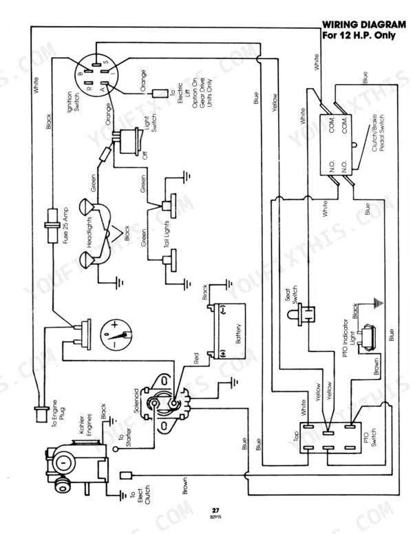
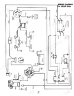
| Wiring Diagrams | 26-27 | Solenoid, Ignition Switch, Battery, P.T.O. Switch, Headlight Switch, Fuse |
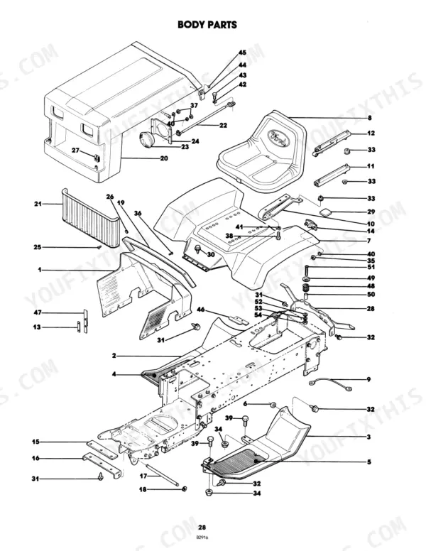
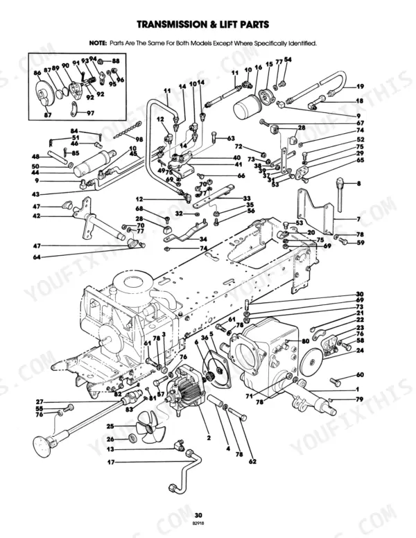
| Body Parts | 28-31 | Transmission and Lift Parts |
| Steering Parts | 32-35 | Brake and Control Parts |
| Front and Rear Wheel Parts | 36-37 | Tire & Wheel Assembly |
| Engine and Gas Tank Parts | 38-41 | Muffler Cover & Decal Assembly, Exhaust Deflector-Top W/Decal |
| Electrical Parts | 42-45 | Wire Assembly (Lights to Ground), Wire Assembly (Harness to Lights) |
| Electric Clutch and Brake Parts | 46-47 | Frame Parts |
| Hydraulic Cylinder Parts | 48-49 | Hydraulic Valve Parts |
| Transaxle Parts | 50-51 | Peerless Model 2548 |
| Safety Decals | 52-56 | Rear Frame Warning, Battery Danger, Operator Seat Warning, Muffler Hot Surface Warning, Model Identification, Ford Logo, Instrument Panel Instructions, Front Trim, Grille Trim, Standard Decals |
Quick Reference Specifications
| Specification | Value | Page |
|---|---|---|
| Fuse capacity | 25 amp | p. 14 |
| Recommended operating tire pressure | 10 lbs | p. 12 |
| Engine oil change interval | 25 hours | p. 16 |
Ford LGT 12H, LGT 17H, LGT 09GN2205, LGT 09GN2206 Common Problems This Manual Covers
Engine will not crank with the controls set correctly
The interlock lets the engine start only with the clutch-brake pedal fully depressed, the P.T.O. switch in the OFF position and the ignition switch turned to START; if it will not start with the controls in those positions, check for a broken, loose or disconnected wire (page 24). For an engine that will not crank the troubleshooting chart lists the clutch-brake pedal and interlock adjustment, the P.T.O. switch, the ignition switch and wiring, a blown fuse and the battery (page 25).
Manual Section: Safety Interlock System p. 24Electric PTO clutch will not engage the mower
If an engine powered attachment fails to engage with the P.T.O. switch on, check the clutch adjustment: with the switch off and the engine stopped and cooled, insert the feeler gauge from the hardware bag through each of the three slots into the gap, where it should go in with a slight amount of resistance. Turn all three lock nuts clockwise 1/4 turn at a time, all equally, and recheck; on 17 HP models the lower exhaust deflector must be removed first (page 21).
Manual Section: Adjustment and Servicing p. 21Brake pedal goes soft or holds poorly
Brake cable adjustment, brake pad adjustment and brake pad replacement are covered in Adjustment and Servicing (page 19). For brakes that do not stop the unit or hold in park, the troubleshooting chart lists a brake that is not adjusted or has worn pads (replace the brake pads) and a stretched or broken brake cable (page 25).
Manual Section: Adjustment and Servicing p. 19Hydrostat creeps or loses ground speed
The hydrostatic drive is adjusted at the factory: the tractor should idle with no movement after the clutch-brake pedal is fully released and neither the forward nor the reverse pedal is actuated, and if it tends to creep, contact your authorized service dealer for correction (page 21). The troubleshooting chart lists the traction drive out of adjustment for creeping in neutral (page 25).
Manual Section: Trouble Shooting p. 21Dead battery, no lights, blown fuse
The electrical system is protected by a 25 amp fuse: an automotive plug type Bussman ATC-25, a Little Fuse type 3AG-25 or a Bussman type AGC-25 (page 14). The wiring diagrams show the solenoid, ignition switch, battery, P.T.O. switch, headlight switch and fuse, so the circuit can be followed with a test light (page 26).
Manual Section: Wiring Diagrams p. 14Routine engine service on the LGT 12H and 17H
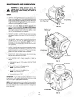
Change the engine oil after the first five hours of operation and every 25 hours after that, ideally just after the engine has been run (page 16). Maintenance and Lubrication also covers the engine oil level, air baffle screen, air cleaner, battery, spark plugs and grease fittings (page 17).
Manual Section: Maintenance and Lubrication p. 16Hard ride or loose hardware from wrong tire pressure
The recommended operating tire pressure is 10 lbs. for both front and rear tires; overinflated tires give a hard-riding tractor and can loosen hardware on the unit (page 12).
Manual Section: Initial Servicing p. 12Frequently Asked Questions
Which Ford tractors does this manual cover?
It covers the Ford LGT 12H and LGT 17H garden tractors, sold under model numbers 09GN2205 and 09GN2206. It is the factory operator book, Ford publication 238242, 56 pages in English. p. 1
Are wiring diagrams included?
Yes. The Wiring Diagrams section runs two pages and shows the solenoid, ignition switch, battery, P.T.O. switch, headlight switch and fuse. Pair it with the Safety Interlock System pages when you are chasing a no-start. p. 26
Does it list part numbers I can order from?
Yes. Component Parts Lists take up pages 28 through 51, with exploded groups for body, transmission and lift, steering, brake and controls, front and rear wheels, engine and gas tank, and electrical parts. p. 28
How is the electric PTO clutch adjusted on the Ford LGT 12H and 17H?
With the P.T.O. switch off and the engine stopped and cooled, insert the feeler gauge from the hardware bag through each of the three slots into the clutch gap; it should go in with a slight amount of resistance. The page text prints the gauge as 0.12 inch while the Figure 20 callout reads .012, so use the gauge supplied with the tractor. Adjust by turning all three lock nuts 1/4 turn at a time, equally. p. 21
How will I receive this Ford LGT 12H, 17H Operator Manual?
Instant PDF download. You get the full 56-page searchable Operator Manual immediately after payment. Open it on your laptop, tablet, or phone right in the shop.
Are there any print restrictions on this Ford LGT 12H, 17H manual?
Yes, print as many copies as you want, and there are no restrictions. Many mechanics print the section they need and bring it to the shop floor.


Reviews
There are no reviews yet.