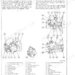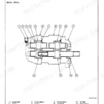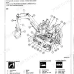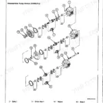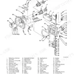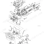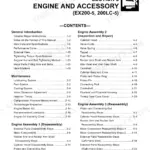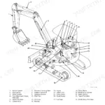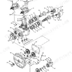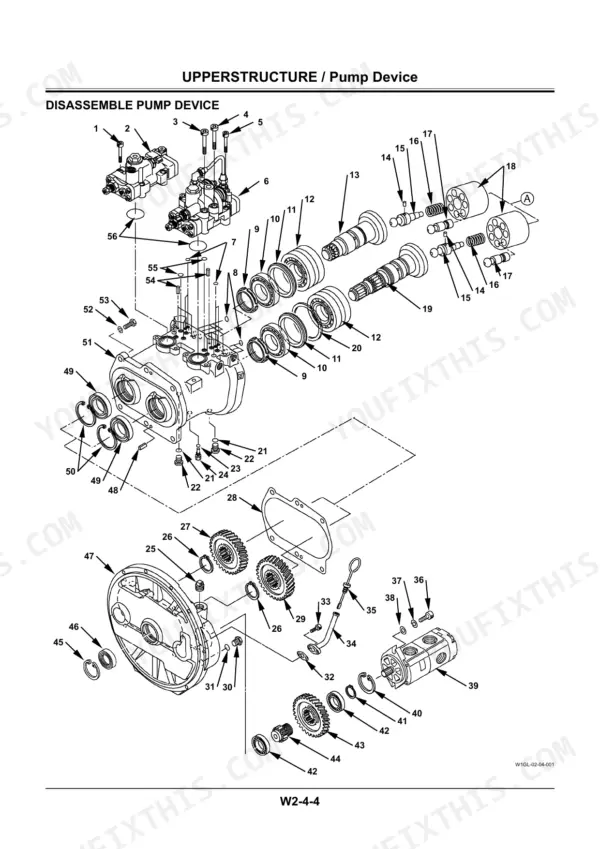

Part of the Hitachi Repair Manuals.
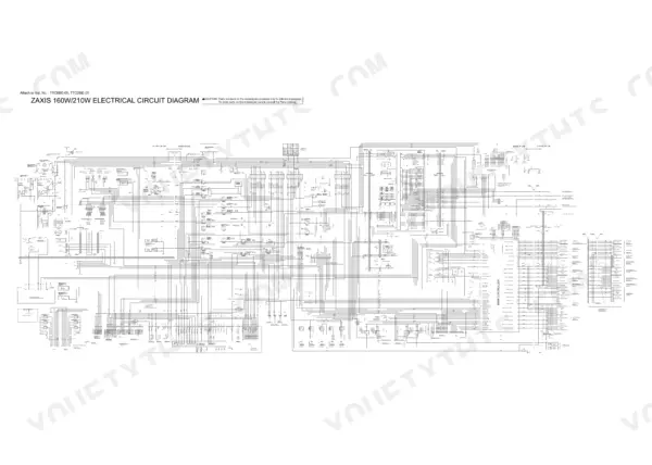
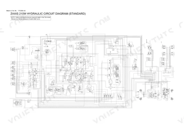
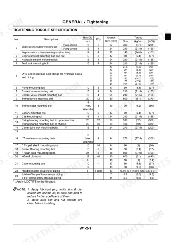
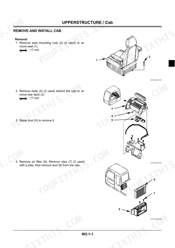
All 718 pages of this Hitachi Zaxis 160W, Zaxis 210W workshop manual PDF focus on one job: complete teardown and repair of your wheeled hydraulic excavator, from cab to counterweight. You get full electrical circuit diagrams tracing the battery, starter, glow relay, main controller, and fuse box, plus hydraulic schematics mapping the main pump, control valve, swing motor, and every cylinder on the front attachment. Inside: step-by-step procedures for the travel motor, swing bearing, center joint, transmission, axles, and brake valve, and a full engine section running from assembly through turbocharger, fuel system, and troubleshooting. Torque the control valve mounting bolts to 210 N-m (152 lbf-ft), and swap the pump suction hose every 2 years per the maintenance chart. No more chasing wiring faults with a multimeter and a prayer. Bookmarked and keyword-searchable; jump straight to the spec and get your machine back on its wheels.
What's Inside This Manual
| System | Pages | Key Topics |
|---|---|---|
| Safety | 3-34 | |
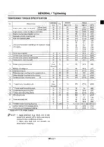
| General | 35-60 | Precautions for Disassembling and Assembling, Tightening, Painting, Bleeding Air From Hydraulic Oiltank |
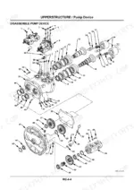
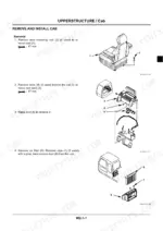
| Upperstructure | 61-262 | Cab, Counterweight, Main Frame, Pump Device |
| Undercarriage | 263-404 | Swing Bearing, Travel Motor, Center Joint, Transmission |
| Front Attachment | 405-472 | Cylinder, Hose-Rupture Safety Valve, Operate-Check Valve |
| Engine and Accessory | 473-700 | General Information, Maintenance, Engine Assembly 1, Engine Assembly 2 |
| Revision Request Form | 701-702 | Company Name, Model, Publication Number, Page Number, Comments |
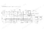
| Circuito Elettrico (1) | 703-714 | Battery, Starter, Alternator, Glow Relay, Main Controller, Fuse Box |
| Circuito Elettrico (2) | 715 | Starter Switch, Wiper Motor, Horn, Combination Switch, Monitor, Pressure Switch |
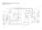
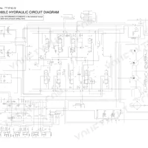
| Circuito Idraulico Full Option | 716 | Main Pump, Control Valve, Swing Motor, Travel Motor, Boom Cylinder, Arm Cylinder |
| Hydraulic Circuit Diagram, Zaxis 210W (Standard) | 717 | Drawing Wcla-0567-Zx, Standard Machine Configuration, Main Pump and Control Valve Circuit, Swing and Travel Motors, Boom/Arm/Bucket Cylinders, Relief Valve Set Pressures (See Technical Manual Table) |
| Hydraulic Circuit Diagram, Zaxis 210W (Full Option) | 718 | Drawing Wcla-0568-Zx, Full Option Configuration, Main Pump and Control Valve Circuit, Swing and Travel Motors, Auxiliary/Attachment Lines, Relief Valve Set Pressures (See Technical Manual Table) |
Quick Reference Specifications
| Specification | Value | Page |
|---|---|---|
| Fuel hose (Fuel tank to filter) replacement interval | Every 2 years | p. 53 |
| Fuel hose (Fuel tank to injection pump) replacement interval | Every 2 years | p. 53 |
| Pump suction hose replacement interval | Every 2 years | p. 53 |
| Control valve mounting bolts | 210 N⋅m (21 kgf⋅m, 152 lbf⋅ft) | p. 117 |
| Fuel filter additional turn | 2/3 of a turn | p. 504 |
| Drain Plug Torque | 9-15 N·m (0.9-1.5 kgf·m/7-11 lb·ft) | p. 506 |
| Engine Oil Viscosity (Ambient -30°C to -15°C) | SAE 10W | p. 517 |
| Engine Oil Viscosity (Multi-grade -30°C to 30°C) | SAE 10W-30 | p. 517 |
| Engine Oil Viscosity (Multi-grade -15°C to 30°C) | SAE 15W-40, 20W-40, 20W-50 | p. 517 |
| Lubricating Oil Volume (Oil Pan) | 21.5 L | p. 45 |