


Part of the Hitachi Repair Manuals.
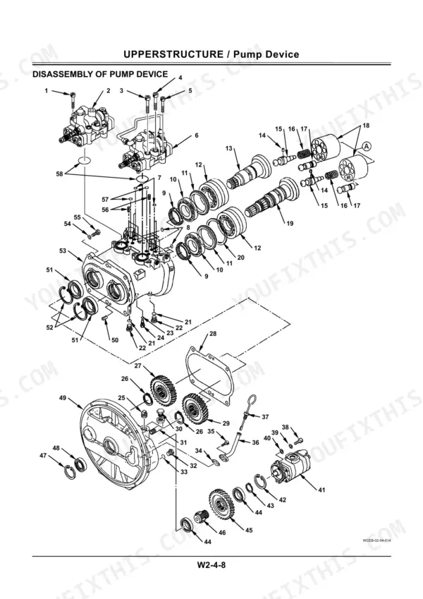
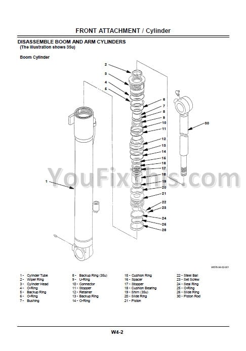
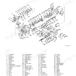
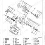
An hour from now you could have this Hitachi ZX170W-3, ZX190W-3 shop manual PDF (OEM WCGB-E-00, 605 pages) open at the bench, tracing a pump device teardown on your wheeled hydraulic excavator. Disassembly and assembly procedures carry the book: control valve on both the 4-spool and 5-spool sides, swing device and swing motor, travel motor, transmission, front and rear axles, and the boom, arm, and bucket cylinders, each sequence closing on maintenance standards. Front attachment work gets its own section, from hydraulic pressure release procedures through hose rupture valve service to standard pin dimensions for arm and bucket connections. Rig the ZX170W-3 counterweight at its listed 3600 kg, and pull a weeping 22 mm union nut to 69 N·m instead of snugging it by feel. A parked excavator burns payroll by the hour. Print what you need; these pages can take grease, while the bookmarked, text-indexed file stays clean on your laptop.
What's Inside This Hitachi ZX170W-3, ZX190W-3 Manual
| System | Pages | Key Topics |
|---|---|---|
| Introduction | 3-4 | Additional References, Manual Composition, Page Number, Safety Alert Symbol and Headline Notations, Units Used |
| Safety | 5-34 | Recognize Safety Information, Understand Signal Words, Follow Safety Instructions, Prepare for Emergencies, Wear Protective Clothing, Protect Against Noise, Inspect Machine |
| General Information | 35-64 | Precautions for Disassembling and Assembling, Maintenance Standard Terminology, Tightening Torque Specifications, Torque Chart, Piping Joint, Periodic Replacement of Parts, Painting, Bleeding Air From Hydraulic Oil Tank |
| Upperstructure, Cab and Counterweight | 65-96 | Removal and Installation of Cab, Dimensions of Cab Glass, Removal and Installation of Counterweight |
| Upperstructure, Main Frame and Pump Device | 97-146 | Removal and Installation of Main Frame, Removal and Installation of Pump Device, Disassembly and Assembly of Pump Device, Disassembly and Assembly of Regulator, Structure of Pilot Pump |
| Upperstructure, Control Valve | 147-198 | Removal and Installation of Control Valve, Disassembly of Control Valve 4-Spool Side, Disassembly of Control Valve 5-Spool Side, Assembly of Control Valve |
| Upperstructure, Swing Device | 199-234 | Removal and Installation of Swing Device, Disassembly and Assembly of Swing Device, Disassembly and Assembly of Swing Motor |
| Upperstructure, Pilot Valve and Electric Controls | 235-282 | Removal and Installation of Pilot Valve, Travel Pilot Valve, Assembly of Front/Swing Pilot Valves, Auxiliary/Positioning Pilot Valves, Electric Lever, Signal Control Valve |
| Upperstructure, Solenoid, Steering and Brake Valves | 283-334 | Shockless Valve, 3-Spool Solenoid Valve Unit, Pilot Shut-Off Solenoid Valve, Steering Valve, Brake Valve, Accumulator Charge Valve |
| Undercarriage, Swing Bearing, Travel Motor and Center Joint | 335-379 | Removal and Installation of Swing Bearing, Disassembly and Assembly of Travel Motor, Disassembly and Assembly of Brake Valve, Center Joint |
| Undercarriage, Transmission, Axles and Propeller Shaft | 380-488 | Removal and Installation of Transmission, Disassembly and Assembly of Transmission, Disassembly and Assembly of Front Axle, Disassembly and Assembly of Rear Axle, Axle Lock Cylinder, Operate Check Valve, Outrigger/Blade Solenoid Valve Unit, Propeller Shaft |
| Front Attachment | 489-605 | Hydraulic Circuit Pressure Release Procedure, Front Attachment (Monoblock Boom), Front Attachment (2-Piece Boom), Removal and Installation of Cylinder, Disassembly and Assembly of Positioning Cylinder, Hose Rupture Valve, Operate Check Valve (for Blade and Outrigger) |
Quick Reference Specifications
| Specification | Value | Page |
|---|---|---|
| All Models | ||
| Light load operation time | 10 to 15 minutes | p. 41 |
| Tightening Torque for Union Nut (19 mm) | 29.5 N·m (3.0 kgf·m, 21.5 lbf·ft) | p. 53 |
| Tightening Torque for Union Nut (22 mm) | 69 N·m (7.0 kgf·m, 51 lbf·ft) | p. 53 |
| Gear oil drain amount | 1.0 L (0.3 US gal) | p. 111 |
| Upperstructure weight | 4800 kg | p. 98 |
| Pump device weight | 195 kg | p. 104 |
| Swing device weight | 225 kg | p. 200 |
| Front axle weight | 650 kg | p. 418 |
| Rear axle weight | 600 kg | p. 422 |
| Axle casing weight | 96 kg | p. 433 |
| ZX170W-3 | ||
| Counterweight weight | 3600 kg | p. 92 |
| ZX190W-3 | ||
| Counterweight weight | 4200 kg | p. 92 |
Hitachi ZX170W-3, ZX190W-3 Common Problems This Manual Covers
Hitachi ZX170W-3 hydraulic oil leaking near engine bay, hoses wet along undercarriage
Inspect every hose along the frame rails for rub marks and wet fittings before condemning the pump. Release circuit pressure, then retorque leaking 19 mm union nuts to 29.5 N·m (21.5 lbf·ft) using the piping torque tables on page 53. Tighten worm gear band clamps to 5.9 to 6.9 N·m and replace any hose with a chafed cover.
Manual Section: General Information p. 53Boom and arm sluggish, all functions slow after hydraulic oil change or pump work
Check hydraulic oil level and bleed air from the hydraulic oil tank after any oil change or pump work; aerated oil makes every circuit lazy. Run the machine at light load for 10 to 15 minutes as specified on page 41 before judging performance. If sluggishness persists at full operating temperature, remove the pump device for disassembly and inspection.
Manual Section: Pump Device p. 41Engine hard to start, cranks fine but low power and weak throttle response under load
Check the fuel lines and pipes for kinks, chafe and loose clamps between tank and injection pump; air drawn into a suction line kills starting. Retorque loose 19 mm line union nuts to 29.5 N·m (21.5 lbf·ft) using the piping torque table on page 53, and tighten worm gear band clamps to 5.9 - 6.9 N·m. Fuel hoses are on the periodic replacement list in General Information (page 56) — replace them on schedule rather than chasing the symptom twice. Injection pump and injector work itself is not in this book: Hitachi publishes the engine service separately, and this Shop Manual points you to the Engine Manual for it (page 3).
Manual Section: General Information p. 53Swing motor groans on takeoff and upperstructure drifts past the stop point
Inspect the swing bearing mounting bolts and check gear bath grease condition first; a dry bearing mimics motor failure. If the motor is at fault, release circuit pressure, then remove the swing device for disassembly. Rig it properly, the assembly weighs 225 kg (page 200), and inspect the swing dampener valve while it is on the bench.
Manual Section: Swing Device p. 200Boom cylinder weeps at the rod and boom settles under load overnight
Measure boom drift with the bucket loaded and controls in neutral; a leaking control valve spool settles the boom too. Release circuit pressure using the procedure in the Front Attachment section starting on page 489, then check the cylinder line fittings and torque 32 mm union nuts to 137 N·m (101 lbf·ft). Reseal the cylinder if the rod stays wet.
Manual Section: Front Attachment p. 489Frequently Asked Questions
What is the torque specification for the engine cushion rubber mounting nut on a Hitachi ZX170W-3?
The torque specification for the engine cushion rubber mounting nut (14 mm bolt diameter) on the Hitachi ZX170W-3 is 140 N·m (14.0 kgf·m, 103 lbf·ft). p. 47
What is the periodic replacement interval for hydraulic hoses on the Hitachi ZX170W-3 and ZX190W-3?
All hydraulic hoses, including pump suction, delivery, swing, travel, and cylinder line hoses, should be replaced every 2 years or every 6000 hours, whichever comes first. p. 56
How do I bleed air from the hydraulic pump?
Remove the air bleeding plug from the top of the pump and fill the pump housing with hydraulic oil. After filling, temporarily tighten the plug, start the engine, and run at slow idle. Slightly loosen the plug until hydraulic oil oozes out, then securely tighten the plug. p. 40
What is the torque specification for the swing device mounting bolt on a ZX170W-3?
The torque specification for the swing device mounting bolt (20 mm bolt diameter) on the ZX170W-3 is 500 N·m (51 kgf·m, 370 lbf·ft). p. 47
What is the gear oil capacity for the transmission on the Hitachi ZX170W-3?
The gear oil capacity for the transmission is 2.5 L (0.7 US gal). p. 382
What do I get after purchasing this Hitachi ZX170W-3 manual?
You download the Shop Manual yourself: 605 pages, searchable PDF, available immediately. Keep a copy on every device you use.
Am I free to print this Hitachi ZX170W-3 Shop Manual?
Yes. Print individual pages or full chapters for your own shop use, on letter or A4 paper.
Reviews
There are no reviews yet.