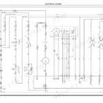
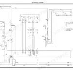
Keeping a Hyster W40XT pallet truck in service is the single job behind these 414 pages, which share coverage with the wider XT series of trucks. Wiring, cabling and schematic diagrams in this Hyster W40XT service manual PDF trace each electrical circuit with its sequence of operation and fault procedures, while hydraulic schematics lay out the lifting mechanism. Curtis transistor motor controller troubleshooting walks through thermal protection and the power circuit, and the fastener section gives metric and inch torque tables with conversion charts. Set shoe to drum clearance at 0.127 mm (0.005 in.). Then hold the brake release cam to upper adjusting nut gap between 0.38 and 0.76 mm (0.015 to 0.030 in.). Maybe your job is brake linkage removal and cable installation; that sequence is written out for each model group. Bookmarked and text-searchable, the pages also print cleanly, so you can keep a working paper copy of whichever section you need.
What's Inside This Manual
| System | Pages | Key Topics |
|---|---|---|
| Brakes | 1-24 | Repairs - General, Brake Shoe Assembly, Brake Shoe Removal, Brake Shoe Installation, Brake Linkage Removal, Brake Linkage and Cable Installation, Brake Adjustment, Brake Linkage Adjustment, Brake Operation, Service Brake, Parking Brake, Checking Brake Clearance, Adjusting Brake Clearance, Troubleshooting Chart, Repair Procedures, Checks, Adjustments, Snap Rings, Steering Control Handle |
| Curtis Transistor Motor Controller | 25-74 | General, Principles of Operation, Transistor Controller, Thermal Protection, Power Circuit, Troubleshooting |
| Electrical System | 75-104 | Circuit Schematics, Sequence of Operation, Fault Procedures, Electrical Components |
| Industrial Battery | 105-132 | Battery Maintenance, Charging, Safety Precautions, Battery Specifications, Troubleshooting |
| Metric and Inch (SAE) Fasteners | 133-152 | Fastener Identification, Torque Tables, Cotter Pins, Conversion Tables |
| Diagrams | 153-214 | Wiring Diagrams, Cabling Diagrams, Schematic Diagrams, Electrical Components |
| Capacities, Specifications, and Maintenance | 215-224 | Hydraulic System, Weight, Torque Specifications, Lifting Mechanism, Troubleshooting, Tires |
| Brakes (W40XT and W45XT) | 225-236 | Top Steer Handle |
| Capacities and Specifications (W40XT and W45XT) | 237-240 | |
| Diagrams with ELM | 241-276 | Wiring Schematic, Options Schematic, Optional Wiring |
| Frame | 277-307 | |
| Lifting Mechanism (W40XT and W45XT) | 308-319 | |
| Lifting Mechanism (B/C60-80XT) | 320-339 | Tandem Wheels |
| Master Drive Unit (MDU) | 340-349 | |
| Periodic Maintenance | 350-373 | Maintenance Schedule, Wheels and Bearings, Motor Brushes |
| Steering Mechanism (W40XT and W45XT) | 374-385 | Flow Regulator Valve, Steering Relief Valve |
| Steering Mechanism (W60-80XT) | 386-400 | |
| Walkie Hydraulic Systems | 401-414 | Control Valve |
Quick Reference Specifications
| Specification | Value | Page |
|---|---|---|
| Brake release cam to upper adjusting nut clearance | 0.38 to 0.76 mm (0.015 to 0.030 in.) | p. 17 |
| Brake shoe to brake drum clearance | 0.127 mm (0.005 in.) | p. 18 |
| Control wire size | 1.5 mm2 (AWG 16 gauge) | p. 101 |
| Alternative control wire size | 1 mm2 (18 gauge) | p. 101 |
| 24 V battery cell potential difference | 2 volts | p. 113 |
| Bicarbonate of soda solution concentration | 0.5 kg of soda for every 4 liters of water | p. 116 |
| Specific gravity of a fully charged battery | 1.265 to 1.310 at 25°C (77°F) | p. 369 |
| Drive Wheel Capscrews Torque | 190 to 217 N•m (140 to 160 lbf ft) | p. 221 |
| Motor and Solenoid Terminal Nuts Torque | 9 N•m (7 lbf ft) | p. 221 |
| Motor Mount Screws, Capscrew (2) | 19 N·m (14 lbf. ft.) | p. 8 |
| Motor Mount Screws, Hex Socket (1) | 19 N·m (14 lbf. ft.) | p. 8 |
| Hydraulic Tank Capacity | 0.95 Litres (1.0 qt.) | p. 238 |