

This is the Isuzu Workshop Manual for the AU-4LE2 and BV-4LE2 industrial diesel engines, a 211-page PDF you can download and keep for reference. These common rail engines are used in generator sets and industrial machinery, and the manual carries them from engine mechanical work through the electrical, exhaust, lubrication, intake, and preheating systems.
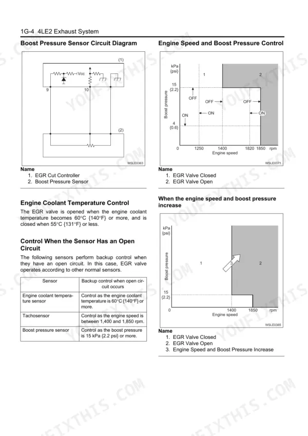
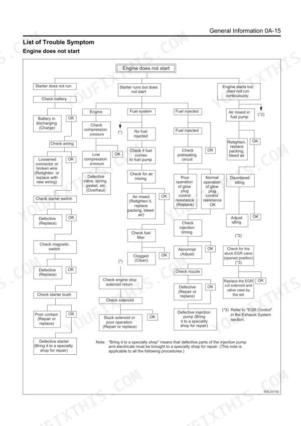
Inside you get the engine mechanical, cooling, fuel, and electrical sections plus dedicated exhaust, lubrication, intake, and preheating chapters. It includes compression figures, cylinder head bolt torque with angle tightening, valve clearance, injection timing and pressure, and the boost pressure and EGR control details for diagnosis and repair.
For owners and mechanics servicing the 4LE2 in gensets or equipment, it provides the factory sequences and specifications needed to trace faults, set the engine correctly, and complete an overhaul.
What's Inside This Isuzu AU-4LE2, BV-4LE2 Manual
| System | Pages | Key Topics |
|---|---|---|
| Isuzu Diesel Engine | 39-49 | Function Check, Inspection of Compression Pressure |
| Engine Exterior Equipment | 50-75 | Engine Accessories |
| Cylinder Head | 76-94 | Rocker Arm Shaft |
| Piston and Connecting Rod | 95-106 | Reassembly and Installation |
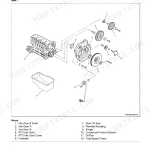
| Crankshaft Front Oil Seal | 107-114 | Flywheel |
| Timing Gear Train | 115-122 | Crankshaft Rear Oil Seal |
| Crankshaft | 123-134 | Camshaft |
| Special Tool | 135-138 | Cylinder Block |
| Cooling System | 139-148 | Service Precautions, Function Check, Water Pump, Thermostat |
| Fuel System | 149-162 | Service Precautions, Explanations on Functions and Operation, Governor, Components |
| Electrical System | 163-193 | Charging System, Generator (24V-30A), Generator (24V-50A), Generator (12V-20A) |
| Exhaust System | 194-199 | EGR Control, Connector Pin Layout, Boost Pressure Sensor Circuit Diagram, Inspection |
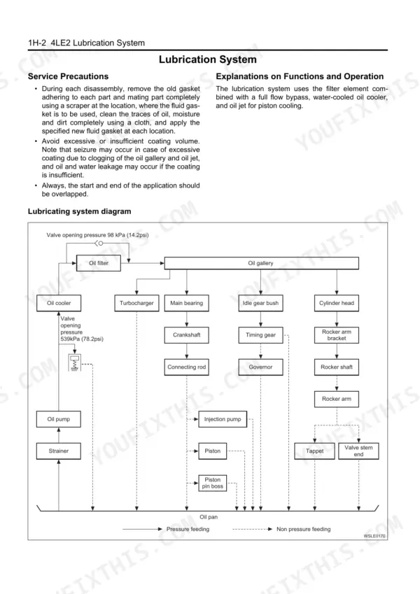
| Lubrication System | 200-204 | Service Precautions, Function Check, Oil Filter, Oil Pump |
| Intake System | 205-207 | |
| Preheating System | 208-211 | Explanations on Functions and Operation |
Quick Reference Specifications
| Specification | Value | Page |
|---|---|---|
| All Models | ||
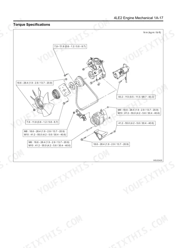
| Generator mounting bolt tightening torque (M10) | 41.2 — 55.0 N·m {4.2 — 5.6 kgf·m/ 30.4 — 40.6 lb·ft} | p. 167 |
| Cylinder head bolt tightening torque (M12 × 1.5) | 83.4 — 93.2 N·m {8.5 — 9.5/ 61.5 — 68.7} → 60° — 90° | p. 26 |
| Boost pressure sensor backup control (open circuit) | Control as the boost pressure is 15 kPa {2.2 psi} or more. | p. 197 |
| Lubrication oil pressure (at 1,000 rpm) | 147 {21} kPa {psi} | p. 36 |
| Thermostat working start temperature (at barometric pressure) | 82°C {180°F} | p. 32 |
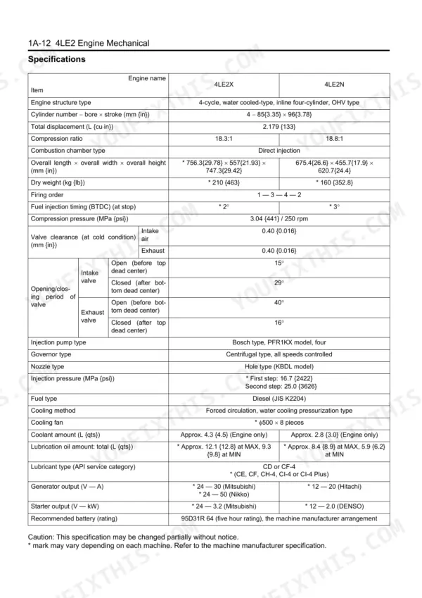
| Compression Pressure (Standard) | 3.04 MPa | p. 25 |
| Compression Pressure (Service Limit) | 2.5 MPa | p. 25 |
| Cylinder Head Bolt Torque (M12 x 1.5) | 83.4 - 93.2 N·m, then angle tighten 60° - 90° | p. 26 |
| Valve Clearance (Cold) | 0.40 ± 0.05 mm | p. 41 |
| 4LE2X | ||
| Engine Oil Capacity, 4LE2X | 9.3 - 12.1 L | p. 15 |
| Fuel Injection Timing (Btdc) | 2° | p. 49 |
| 4LE2N | ||
| Engine Oil Capacity, 4LE2N | 5.9 - 8.4 L | p. 15 |