
Part of the JCB Repair Manuals.
JCB wrote this factory service manual for its own dealer technicians. It covers the 506-36, 507-42, 509-42, 510-56 and 512-56 Loadall, starting with safety procedures, maintenance positions and serial number checks and ending with the hydraulic and electrical schematics.
Every hour a Loadall sits with a warning light on is lifting work that doesn't get done. This book covers JCB Servicemaster diagnostics and the ECM fault code table. It also shows how to discharge the accumulator before you open a hydraulic line, and gives the lift arm torque table. Engine, fuel, cooling, brakes, steering, driveline and cab HVAC each have their own section.
You buy it once and keep it for as long as you run this machine.
What's Inside This JCB 506-36 to 512-56 Manual
| System | Pages | Key Topics |
|---|---|---|
| Spine Cards | 3-6 | Volume 1, Volume 2, Volume 3, Volume 4 |
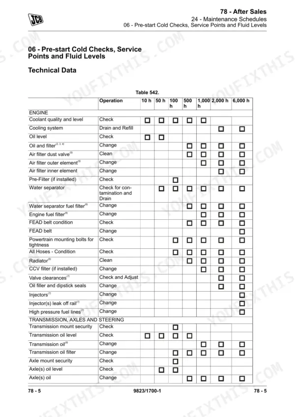
| Machine | 7-40 | Safety Procedures, Maintenance Positions, Model and Serial Number Identification, Cleaning and Preparation, General Description |
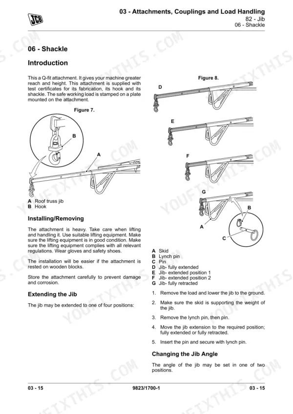
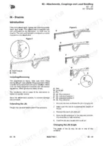
| Attachments, Couplings and Load Handling | 41-66 | General Attachment Safety, Mechanical Tow Hitch, Fork Adjustment and Operation, Jib and Shackle Usage, Hook and Snatch Block |
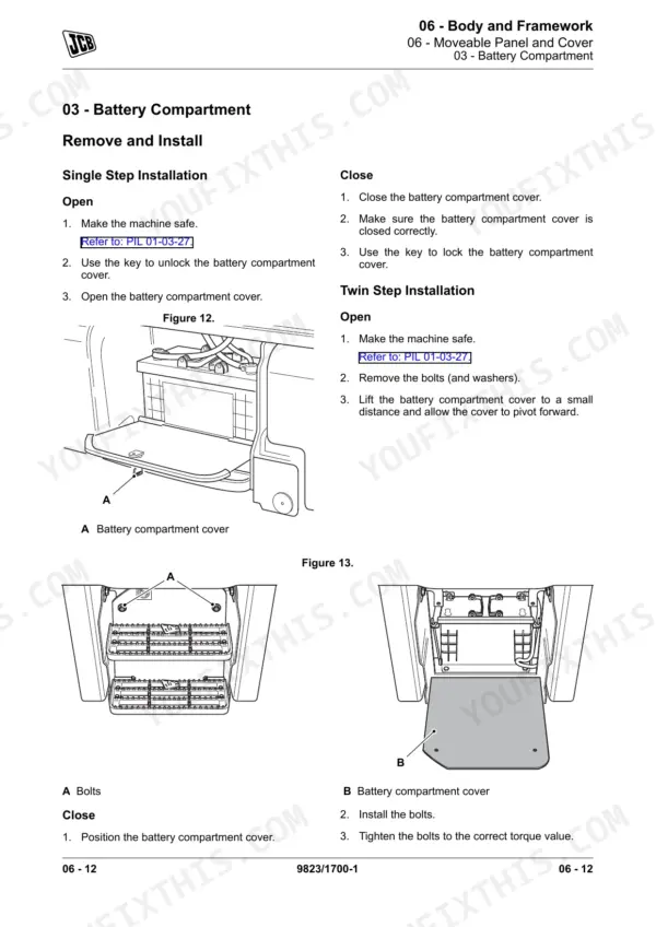
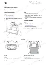
| Body and Framework | 67-224 | ROPS/FOPS Cab, Main Component Locations, Service Point Locations, Grease Point Maintenance |
| Operator Station | 225-290 | Cab Frame, Operator Protective Structure, Window, Operator Seat, Seat Belt, Door, Controls, Trim Panel |
| Heating Ventilating and Airconditioning HVAC | 291-370 | HVAC Unit, Heater Unit, Compressor, Receiver Drier, Condenser, Heater Valve |
| Engine | 371-660 | Fuel System Safety, Exhaust Gases, Hot Components, Engine Maintenance Safety |
| Fuel and Exhaust System | 661-768 | Throttle Control System, Water Separator, Injection, Fuel Pump, Turbocharger, Fuel Cooler |
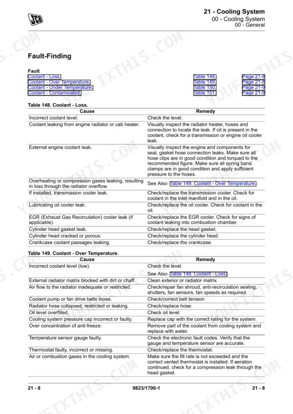
| Cooling System | 769-834 | Cooling Pack, Transmission Oil Cooler, Fan Motor, Expansion Tank, Thermostat |
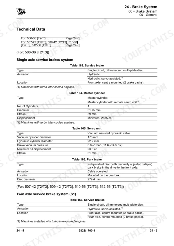
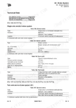
| Brake System | 835-902 | Service Brake, Master Cylinder, Vacuum Servo Unit, Vacuum Pump, Park Brake |
| Steering System | 903-984 | Manual Steer Mode System, Priority Valve, Steer Unit/Valve, Mode Valve, Proximity Switch, Front Track Rod |
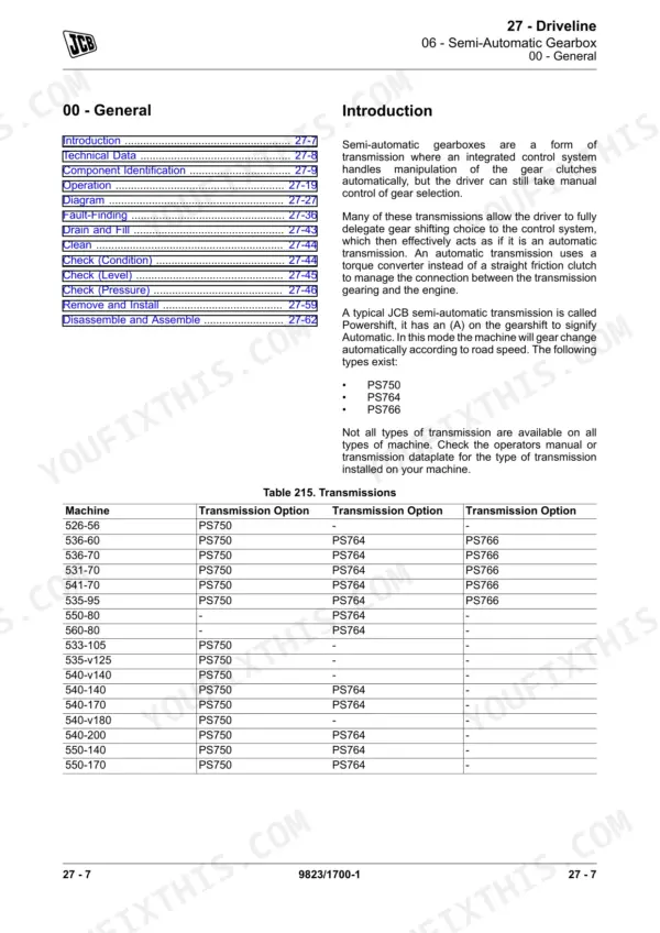
| Driveline | 985-1366 | Semi-Automatic Gearbox, Transfer Gearbox, Torque Converter, Axle(s), Differential, Hub, Propshaft |
| Hydraulic System | 1367-1656 | Hydraulic Pressure Safety, Hydraulic Hose Maintenance, Accumulator Discharge, Schematic Circuit References |
| Electrical System | 1657-2254 | Battery and Isolator Switch, Power Distribution, Arc Welding Precautions, Electronic Diagnostic Tools |
| Fasteners and Fixings | 2255-2280 | Screws, Bolts, Clips, Threaded Insert |
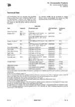
| Consumable Products | 2281-2310 | Grease, Locking Fluids, Sealant, Fuel |
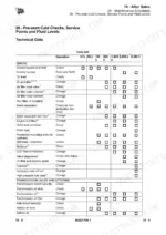
| After Sales | 2311-2364 | Maintenance Schedules, Maintenance Intervals, Personal Protective Equipment (PPE), Special Tools, Non JCB Tools, Units of Measurement |
Quick Reference Specifications
| Specification | Value | Page |
|---|---|---|
| Wheel nut torque (506-36, 507-42, 509-42, 510-56, 512-56) | 680 N·m | p. 1343 |
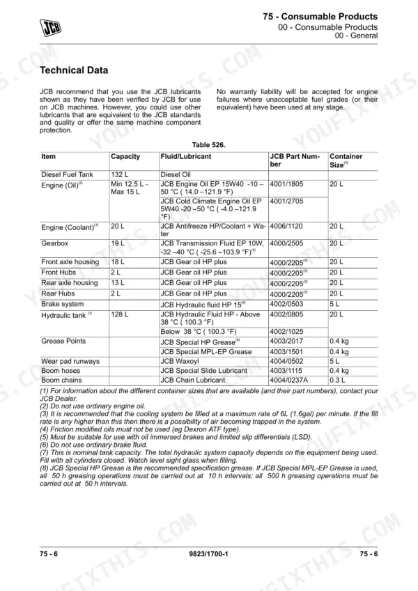
| Diesel fuel tank capacity | 132 L | p. 2286 |
| Gearbox oil capacity | 19 L | p. 2286 |
| Front axle housing oil capacity | 18 L | p. 2286 |
| Rear axle housing oil capacity | 13 L | p. 2286 |
JCB 506-36 to 512-56 Common Problems This Manual Covers
RAS ECU memory fault with the ECU running on default data
This fault means the ECU has lost its stored data and fallen back to defaults, so the machine may not behave the way it was set up. The Electronic Diagnostic section shows how to load the correct data back onto the ECU with JCB Servicemaster. Clear the logged code afterwards and check that it stays clear.
Manual Section: Electrical System - Electronic Diagnostic p. 1420Audible or visual warning comes on with the engine running
Stop the engine as soon as it is safe, as the manual instructs. Connect Servicemaster and read the logged codes on the Fault Codes page. Then look up each one in the fault code table to see its description, which warning it triggers and its severity. The fusebox and ignition schematics help you trace any wiring fault behind the code.
Manual Section: Electrical System - Electronic Diagnostic, Fault Codes and Schematic Circuits p. 2073Stored hydraulic pressure when opening lines or working on the sway/stabiliser circuit
Opening a charged line can throw oil or move a ram without warning. The Hydraulic System chapter covers accumulator discharge and the sway/stabiliser isolation valve, so you can make the circuit safe before you touch a fitting. The main circuit schematic lets you trace each line back to its valve before you start.
Manual Section: Hydraulic System - Schematic Circuits and Accumulator Discharge p. 1431Lift arm pivots running dry or fixings working loose
Dry pins and loose fixings on the boom wear quickly under load and lead to slop at the carriage. The lift arm section of Body and Framework lists the service and grease points and includes a torque values table for the lift arm fixings. Grease every point listed and torque everything to the table.
Manual Section: Body and Framework - Lift Arm, Service and Grease Points p. 129Frequently Asked Questions
How do you clear a fault code on a JCB Loadall?
Connect JCB Servicemaster and open the Fault Codes page. The Erase Fault Codes button wipes the logged codes from the ECM memory. If you're using the data logger tool, select Reset and then Reset error log. Fix the cause first, or the code will just log again. p. 2122
What does an error code mean on a JCB telehandler?
The ECM logs a code when a sensor or actuator signal is not valid. The Fault Codes table in the Electronic Diagnostic section gives each code's description, the warning it brings up on the display and how severe it is. That table tells you whether you can finish the lift or need to park up now. p. 2195
How do you reset the service light on a JCB telehandler?
Service hours are reset with JCB Servicemaster. The procedure is in the Electrical System chapter under Electronic Diagnostic. Do the service first, then reset the hours so the next interval counts from the right point. p. 2084
What are the wheel nut torque specs for the 506-36 to 512-56?
The wheel nut torque is 680 N·m on all five models: 506-36, 507-42, 509-42, 510-56 and 512-56. Use a proper torque wrench, not a rattle gun. A wheel coming loose on a machine carrying a raised load is not something you want to find out about the hard way. p. 1343
A warning buzzer or light came on while the engine was running. What now?
The manual is clear on this: stop the engine as soon as it is safe to do so, and fix the fault before you carry on. Then plug in Servicemaster and read the logged fault codes. Compare them with the fault code table so you're fixing the actual fault, not guessing at it. p. 2073

Reviews
There are no reviews yet.