


Part of the John Deere Repair Manuals.
This is the John Deere factory diagnostic manual (TM2197) for the 5225, 5325, 5425, 5525, 5603 and 5625 utility tractors, published August 2010. Across 1,889 pages it covers every diagnostic trouble code logged by the CCU, HCU and PTR electronic control units, symptom-based diagnostic trees for all major systems, and step-by-step tests and adjustments for the engine, electrical circuits, SyncShuttle and PowerReverser transmissions, drive systems, steering, brakes, hydraulics and operator station. Full functional schematics and connector pinout diagrams for both cab and open-station configurations are included - the same information a John Deere dealer technician uses to trace an intermittent fault from the first DTC to the confirmed root cause.
What's Inside This John Deere 5225-5625 Manual
| System | Pages | Key Topics |
|---|---|---|
| General | Safety, General Specifications, Bolt and Cap Screw Torque Values, Glossary of Terms, Electrical Schematic Symbols, Seven-Step Electrical Test Procedure | |
| Diagnostic Trouble Codes | Ccu Code Diagnostics, Hcu Code Diagnostics, Ptr Code Diagnostics | |
| Observable Symptoms | Engine Symptoms, Fuel and Air, Electrical Faults, Control Unit Faults, SyncShuttle Transmission, PowerReverser Transmission, Drive Systems, Steering and Brakes, Hydraulics, Operator Station | |
| System Diagnosis | Starting, Charging and Start Aid, SyncShuttle Transmission, PowerReverser Transmission, Differential Lock, MFWD, Rear PTO, Steering, Rear Brakes, Rear SCV, Mid-Mount Control Valve, Rear Hitch, Air Conditioning | |
| Engines | General Engine Specifications, Engine Model/Horsepower Reference, Throttle Lever Adjustment, Foot Throttle Pedal Stop, Engine System Theory of Operation | |
| Fuel and Air | General Information, Fuel and Air Theory of Operation | |
| Electrical | Vehicle Electrical Center and Fuse/Relay Block, Tests and Adjustments, Theory of Operation, Functional Schematics, Connector Information (5225/5325/5425/5525/5625), Connector Information (5603) | |
| Control Units | General References, Tests and Adjustments, Ccu Diagnostics, Hcu Diagnostics, Ptr Diagnostics, VIN Network Address Checks, CAN Communication System | |
| SyncShuttle Transmission | Tests and Adjustments, Theory of Operation, Schematics and Diagrams | |
| PowerReverser Transmission | General Information, Preliminary and Operational Checks, Tests and Adjustments, Theory of Operation, Schematics and Diagrams | |
| Steering and Brakes | General Information, Preliminary and Operational Checks, Test and Adjustments, Theory of Operation | |
| Hydraulics | Pump Flow Test, Main Relief Valve Test, Rockshaft Lift Cycle Test, SCV Tests, Rear Hitch Diagnosis, Theory of Operation, Schematics and Diagrams (5225/5325/5425/5525/5625 and 5603 Variants) | |
| Operator Station | General Information, Preliminary and Operational Checks, Tests and Adjustments, Air Conditioning System Tests, Theory of Operation | |
| Service Tools | Dealer Fabricated Tools, Service Tools and Kits |
Documents This Manual Refers To
The manufacturer cites these publications by number. We carry them:
Quick Reference Specifications
| Specification | Value | Page |
|---|---|---|
| 5225 | ||
| Engine (5225) | 5030PF270 - 3.0 L 5-cylinder turbo, 42 kW (56 hp) | |
| 5325 | ||
| Engine (5325) | 5030PF270 - 3.0 L 5-cylinder turbo, 50 kW (67 hp) | |
| 5425 | ||
| Engine (5425) | 4045TLV53 - 4.5 L 4-cylinder turbo, 60 kW (81 hp) | |
| 5525 | ||
| Engine (5525) | 4045TLV54 - 4.5 L 4-cylinder turbo, 68 kW (91 hp) | |
| 5625, 5603 | ||
| Engine (5625 and 5603) | 4045TLV56 - 4.5 L 4-cylinder turbo, 74 kW (99 hp) | |
| 5225, 5325 | ||
| Hydraulic Pump Flow (5225 and 5325) | 39.3-51.2 Lpm (10.4-13.5 gpm) at 10 345 kPa (1500 psi) load | |
| 5425, 5525 | ||
| Hydraulic Pump Flow (5425 and 5525) | 53.5-69.6 Lpm (14.1-18.4 gpm) at 10 345 kPa (1500 psi) load | |
| All models | ||
| Hydraulic Main Relief Valve Pressure | 18 995-19 685 kPa (190-197 bar / 2,755-2,855 psi) | |
John Deere 5225-5625 Common Problems This Manual Covers
PowerReverser commands neutral unexpectedly or refuses a direction change during operation
Start with the PTR DTC chapter and read the active fault code. Most cases are a sensor reference voltage fault (PTR 001079.03/04) or a solenoid circuit voltage fault triggering the fail-safe neutral command. The PTR Tests and Adjustments chapter covers enable pressure sensor circuit tests and solenoid resistance checks so you can confirm whether the fault is in the wiring, the solenoid itself or the PTR controller before any disassembly.
Manual Section: Diagnostic Trouble Codes - PTRHydraulic system pressure is low or the rear hitch lifts slowly under load
Run the pump flow test from Section 270 first: connect the JT07148 Digital Hydraulic Tester, set engine speed to 2000 rpm and load to 10 345 kPa (1500 psi). If flow is below 39.3 Lpm on a 5225/5325 or below 53.5 Lpm on a 5425/5525, the pump is worn or the filter is clogged. Then run the main relief valve test to confirm outlet pressure is between 18 995 and 19 685 kPa. Address the lowest reading first before condemning larger components.
Manual Section: Hydraulics - Tests and AdjustmentsIntermittent starting failure or no-crank condition with no obvious blown fuse
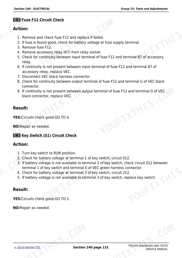
Follow the Seven-Step Electrical Test Procedure in Section 210 and use the Starting and Charging System Diagnosis group in Section 213. Check fuses F1, F18 and the F26 fusible link in the Vehicle Electrical Center first, then test the ELX relay, neutral start relay and key switch circuit. The functional schematic SE1 in Section 240 shows the full starting circuit so you can pinpoint the open or shorted leg with a digital multimeter without chasing individual wires blind.
Manual Section: Electrical - Tests and AdjustmentsCCU fault code after replacing a controller, or VIN security fault preventing normal operation
A VIN security fault occurs when a replacement CCU, HCU or PTR from another tractor is installed without reprogramming. The Control Units section explains how to check VIN Network addresses at CCU address 251, HCU address 251 and PTR address 251 to confirm they all match the tractor's vehicle identification number. If they do not match, program the new controller per Reference 245-05-005 before returning the machine to service.
Manual Section: Control Units - CCUFrequently Asked Questions
How do I read and diagnose a DTC on the John Deere 5425 or 5525?
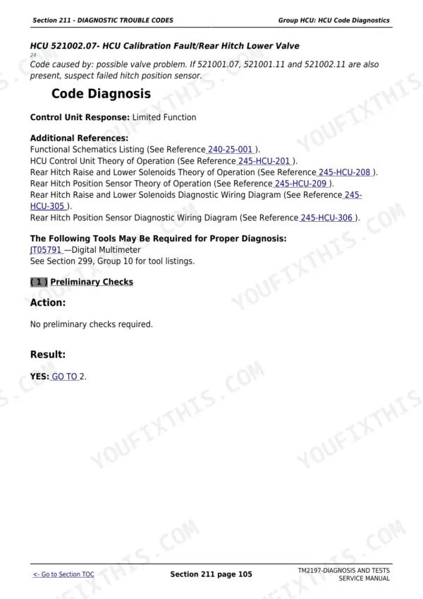
The manual's Diagnostic Trouble Code section (Section 211) lists every CCU, HCU and PTR fault code with its trigger condition and a step-by-step diagnostic tree. Find the code on the display, look it up in the appropriate control unit chapter, and follow the numbered action steps to isolate the failed circuit or component before ordering parts.
Why does the PowerReverser transmission command neutral unexpectedly on a 5525 or 5625?
Most unintended neutral commands trace to a DTC in the PTR controller caused by a solenoid circuit fault, sensor voltage out of range, or a failed enable pressure sensor. The PTR Code Diagnostics chapter and the PowerReverser Tests and Adjustments section walk through checking solenoid resistance, enable pressure, and clutch calibration values so you can confirm the root cause before pulling the transmission.
What hydraulic pump flow and relief pressure should I see when testing the 5225 or 5325?
At 10 345 kPa (1500 psi) load and 2000 rpm, a healthy 5225 or 5325 pump should deliver 39.3-51.2 Lpm (10.4-13.5 gpm). Main relief valve outlet pressure should read 18 995-19 685 kPa (2,755-2,855 psi). The Hydraulics Tests section covers the full procedure including gauge connections and the JT05473 test kit setup.
Does this manual cover the electrical wiring for both cab and open-station 5000 series tractors?
Yes. Section 240 includes full functional schematics and separate connector information chapters for 5225, 5325, 5425, 5525 and 5625 cab/open-station tractors (Group 30) and for the 5603 model (Group 35). The seven-step electrical test procedure and schematic symbol guide in Section 210 give you the method to work through any intermittent circuit fault.
How do I test the MFWD and rear PTO systems on these tractors?
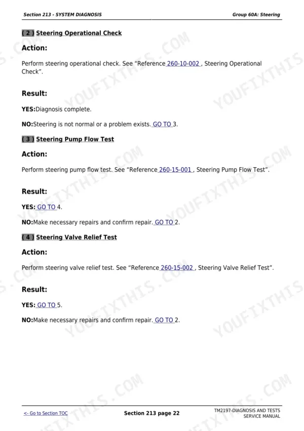
The System Diagnosis section (Section 213) covers MFWD and rear PTO as separate diagnostic groups. The MFWD chapter has both SyncShuttle and PowerReverser transmission variants and walks through clutch engagement checks, solenoid tests and the drive system schematics. The PTO chapter covers the safety interlock, solenoid circuit and control unit outputs so you can differentiate an electrical fault from a mechanical one.
Is this manual a digital download?
You get a 1889-page searchable PDF (74 MB) that downloads instantly after checkout. Open it on your laptop, tablet, or phone, and bring it right to the shop floor.
Can I print specific sections of this John Deere 5225 Diagnostic?
Yes. Print the pages or sections you need for your own shop use. Any standard printer works.








Reviews
There are no reviews yet.