



Part of the John Deere Repair Manuals.
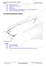
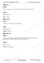
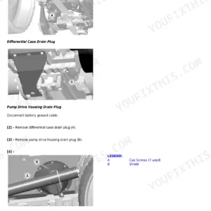
This is the John Deere factory Diagnosis and Tests manual for the 5055E, 5065E, 5075E, 5078E, 5085E and 5090E utility tractors. Its 1,032 pages are organized by system: each section leads with component locations, explains how that system works, then walks through the diagnostic trees, test procedures and adjustment specs the dealer technician follows to pin down a fault. It covers the engine, fuel and air intake, the full electrical system (with separate wiring schematics for each model sub-group), drive train and clutch, brakes and steering, and the hydraulic system with pressure and flow tests. This is the diagnostic edition - it tells you how to find what is wrong. For teardown and rebuild steps, the companion Repair manual covers those procedures.
What's Inside This John Deere 5055E, 5065E, 5075E, 5078E, 5085E, 5090E Manual
| System | Pages | Key Topics |
|---|---|---|
| General Information | Safety Precautions, Component Identification Locations, Manual Navigation | |
| Engine System | Component Location, Theory of Operation, Compression Tests, Oil Pressure Tests, Cooling System Tests, Idle Speed Adjustment, Diagnostic Trouble Codes | |
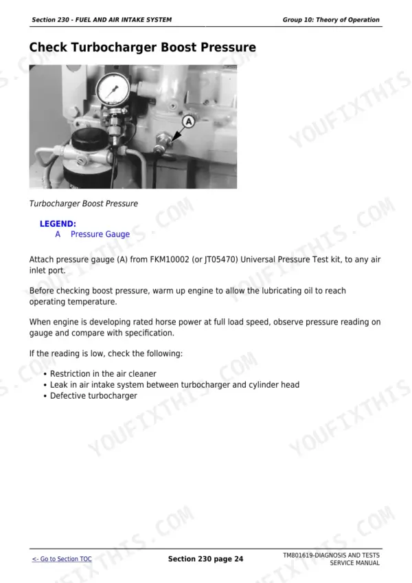
| Fuel and Air Intake System | Fuel Transfer Pump Tests, Injection Nozzle Testing, Air Intake Restriction Diagnosis, Fuel Bleeding Procedures, Fip Synchronization | |
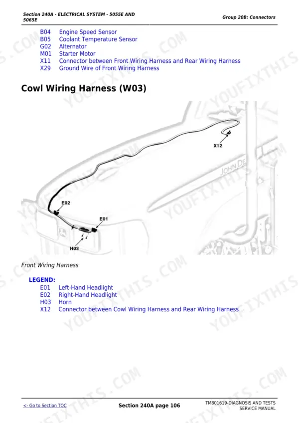
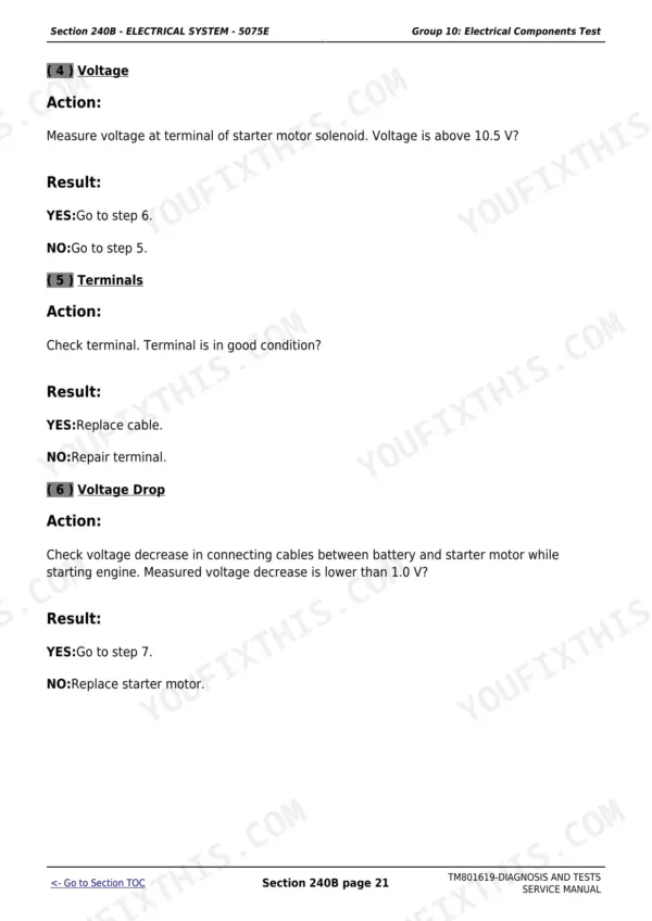
| Electrical System | Wiring Schematics by Model Variant (5055E/5065E, 5075E, 5078E/5085E/5090E), Ccu Fault Codes, Connector and Harness Tests, Neutral Safety Switch Diagnosis | |
| Drive Train | Transmission Component Location, Clutch Free Play Adjustment, MFWD Diagnostics, Power Train Tests and Adjustments | |
| Brake and Steering | Brake Pedal Adjustment, Hydraulic Brake Tests, Brake Pressure Specs, Steering Cylinder Diagnostics | |
| Hydraulic System | Pump Pressure Tests, Valve Block Diagnostics, Hydraulic Schematics, Relief Valve Settings, Flow Tests and Adjustments |
Quick Reference Specifications
| Specification | Value | Page |
|---|---|---|
| Low Idle Engine Speed | 850 +/-25 rpm | |
| Full Load Engine Speed | 2300 rpm | |
| Cylinder Minimum Compression Pressure | 2400 kPa (24 bar / 350 psi) | |
| Maximum Compression Difference Between Cylinders | 350 kPa (3.5 bar / 50 psi) | |
| Valve Clearance - Inlet | 0.35 mm (0.014 in.) | |
| Valve Clearance - Outlet | 0.45 mm (0.018 in.) | |
| Minimum Engine Oil Pressure (at 825 rpm) | 100 kPa (1 bar / 15 psi) | |
| Minimum Engine Oil Pressure (at 2500 rpm) | 277-483 kPa (2.77-4.83 bar / 40-70 psi) | |
| Thermostat Opening Temperature (starts to open) | 71 C (160 F) | |
| Cooling System Test Pressure (maximum apply) | 120 kPa (1.20 bar / 18 psi) |
John Deere 5055E, 5065E, 5075E, 5078E, 5085E, 5090E Common Problems This Manual Covers
Brake pedals sink to the floor with little or no stopping force on 5075E
This is typically caused by internal seal failure in the brake valve or low transmission-hydraulic fluid. The Brake and Steering section covers the hydraulic brake pressure test and seal inspection sequence. Check fluid level first, then measure circuit pressure before disassembling - a simple low-fluid top-up often restores pedal feel on tractors that have not had their fluid checked in a full season.
Manual Section: Brake and SteeringTractor feels sluggish from a stop or slips noticeably under load
Out-of-spec clutch free play is the most common cause on 5E tractors. The Drive Train section covers setting clutch pedal free play to 20-25 mm via the turnbuckle assembly. Adjust to the middle of the range, then test under load. If slip persists after adjustment, the section also covers clutch disc wear inspection to confirm whether a disc replacement is needed rather than another adjustment.
Manual Section: Drive TrainTractor will not start or gear engagement is locked - neutral safety switch suspected
The neutral safety switch (park position sensor, part M132725) fails often enough on 5E tractors to have a dedicated diagnostic path in the Electrical System section. Test the switch circuit at the connector before condemning the switch itself - a corroded connector pin or pinched harness wire produces identical symptoms. Confirm voltage at the sensor pins and check the harness for chafe damage before ordering a replacement part.
Manual Section: Electrical SystemEngine cranks slowly and emits white smoke on cold start or will not start
White smoke with slow cranking points to low compression, a weak glow system, or water-contaminated fuel. The Engine System section covers the compression test (minimum 2400 kPa / 350 psi, maximum 350 kPa between cylinders) and the starter motor minimum speed check (at least 90 rpm). Confirm compression first, then check fuel quality and the glow system before moving on to injector testing.
Manual Section: Engine SystemFrequently Asked Questions
What error codes are common on John Deere 5055E, 5065E and 5075E tractors?
The most frequent codes on 5E Series tractors involve wheel speed detected during transmission calibration, high CCU voltage instability, and neutral safety switch faults that block the starter or gear engagement. The Electrical System section (split by model sub-group) gives the full diagnostic tree for each code, including which connector pins to check before replacing the controller.
How do I diagnose low engine power on a John Deere 5E Series tractor?
The Engine System section walks through the low-power diagnostic tree step by step. Start by confirming full-load engine speed at 2300 rpm, then run a compression test - minimum is 2400 kPa (350 psi) with no more than 350 kPa difference between cylinders. Also check tyre slip: target is 10-15 percent on 2WD and 8-12 percent on MFWD. If compression is good, the Fuel and Air section covers air filter restriction and injection pump synchronization.
Why do the brake pedals go straight to the floor on a John Deere 5075E?
Floor-level brake pedals almost always point to internal seal failure in the brake circuit or low transmission-hydraulic fluid. The Brake and Steering section covers the hydraulic brake pressure test and the seal inspection sequence. Check fluid level first, then measure circuit pressure against the factory spec before pulling the transmission apart - a simple fluid top-up restores pedal feel on tractors that have been neglected.
What is the correct clutch free play on the John Deere 5055E and 5075E?
Clutch free play should be 20-25 mm (roughly 3/4 inch) at the pedal. A tractor that feels weak from a stop or slips under load almost always traces to free play out of this range. The Drive Train section covers the turnbuckle assembly adjustment procedure and the engagement test to confirm the repair is complete.
Does this manual include wiring diagrams for the 5055E, 5075E and 5090E separately?
Yes. The Electrical System section is split into three sub-sections: 240A for the 5055E and 5065E, 240B for the 5075E, and 240C for the 5078E, 5085E and 5090E. Each sub-section has full wiring schematics, connector locations, harness routing, component tests and diagnostic trouble code lookup for the CCU and engine control module specific to that model group.
What exactly do I receive with this John Deere 5055E Diagnostic?
Immediate download of the complete 1032-page searchable Diagnostic (20 MB). Access it on any device, from a laptop at your desk to a phone in the field.
Is this John Deere 5055E manual print-friendly?
Yes. Print the pages or sections you need for your own shop use. Any standard printer works.








Reviews
There are no reviews yet.