
Torque converter and transmission, loading and steering hydraulics, brakes, the center pin articulation joint and the ECM and MODM electronics are each covered from function and structure through check and adjustment in this 701-page shop manual for the Kawasaki 115ZV-2 wheel loader, OEM ID 93216-00462. The last quarter of the Kawasaki 115ZV-2 shop manual PDF is drawings: hydraulic and brake circuits that trace oil from the pumps through the loader valve to the boom and bucket cylinders, plus full electrical wiring diagrams and equipment layouts. ECM fault codes sit next to troubleshooting charts that send each symptom to a gauge check. The return filter relief valve should open at 0.1±0.02 MPa (14±2.8 psi), and M30 grade 8.8 bolts take 1,422 N-m. A wrong pilot valve costs you freight and a second teardown. Bookmarked, text-searchable pages show which serial number break your loader falls under, so you order the right version the first time.
What's Inside This Kawasaki 115ZV-2 Manual
| System | Pages | Key Topics |
|---|---|---|
| General Information | 1-35 | How to Use Manual (Safety Precautions, Symbols) |
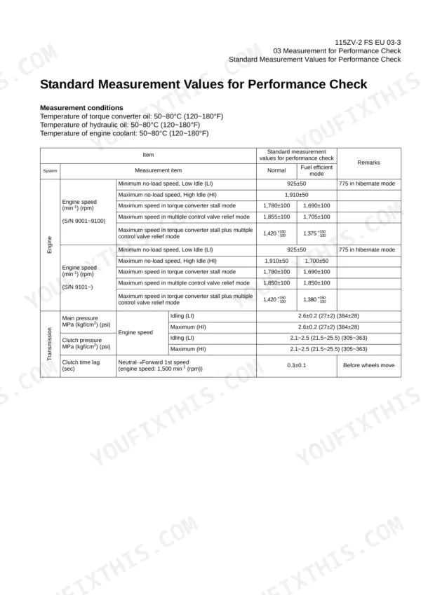
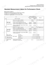
| Measurement for Performance Check | 36-41 | Cautions on Safety, Standard Measurement Values for Performance Check |
| Function & Structure Chassis Group | 42-51 | Front Chassis (Loading Linkage, Loading Linkage Pin), Rear Chassis (Fuel Tank, Floor Board Mount), Center Pin (Upper Center Pin, Lower Center Pin, Dust Seal) |
| Check & Adjustment Chassis Group | 52-59 | Linkage Pin (Liner), Center Pin (Shim, Installing Bearing Cover, Installing Bearing Outer Ring) |
| Function & Structure Power Group | 60-81 | Power Line, Engine / Transmission (Mount), Radiator (Mount), Propeller Shaft (First Propeller Shaft Assembly, Second Propeller Shaft Assembly, Third Propeller Shaft Assembly) |
| Check & Adjustment Power Group | 82-91 | Engine (Measuring Engine: Speed, Oil Pressure), Propeller Shaft (Phase, Second Propeller Shaft Alignment, Tightening Torque) |
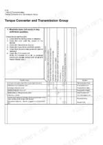
| Function & Structure Torque Converter and Transmission Group | 92-131 | Torque Converter (Structure, Power Flow Path, Torque Multiplication), Torque Converter Gear Pump (Gear Pump Specifications) |
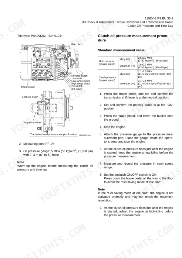
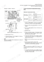
| Check & Adjustment Torque Converter and Transmission Group | 132-135 | Clutch Oil Pressure and Time Lag (Measuring Clutch Oil Pressure) |
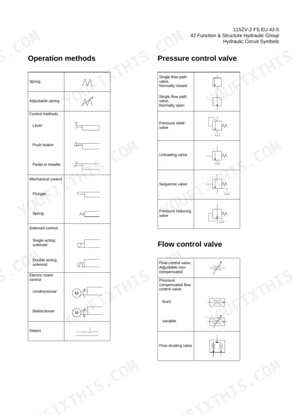
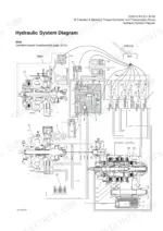
| Function & Structure Hydraulic Group | 136-245 | Flushing Hydraulic Circuit (Purpose of Flushing), Cautions on Hydraulic Parts Replacement |
| Check & Adjustment Hydraulic Group | 246-261 | Loading/Steering Circuit Relief Valve/Ride Control Circuit Reducing Valve (Loading Circuit Relief Valve Setting Pressures, Ride Control Circuit Reducing Valve Setting Pressures, Steering Circuit Relief Valve Setting Pressures) |
| Function & Structure Brake Group | 262-299 | Brake System Outline (Service Brake, Parking Brake, Axle Internal Pressure), Brake Units Layout, Unloader Valve (Operation), Valve Unit, Accumulator |
| Check & Adjustment Brake Group | 300-309 | Brake Circuit Oil Pressure (Unloader Valve Setting Pressure, Brake Valve Oil Pressure) |
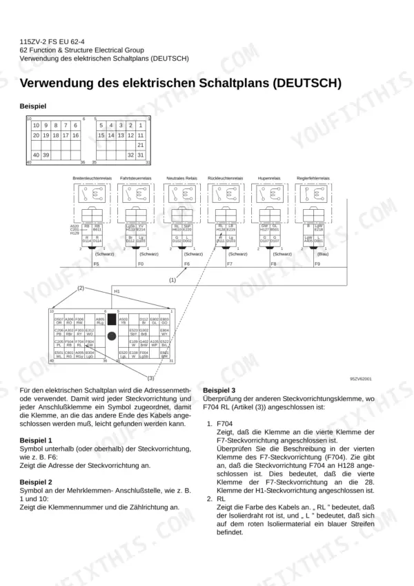
| Electrical Group Fundamentals | 310-321 | Wiring Diagrams, Cable Color Codes, Electrical Circuit Symbols, Sensor Mounts, Fuses, Fusible Links |
| Engine Start and Power Generation | 322-330 | Engine Start Circuit, Neutral Relay, Magnetic Switch, Voltage Relay, Power Generating/Charging Circuit, Alternator |
| ECM and Monitoring System | 331-371 | ECM Function, Failure Diagnosis, Fault Codes, Monitor Lamp Test, Operation Monitor Lamps, Instrument Panel |
| Machine Operation Diagnostic Module (MODM) | 372-417 | MODM Functions, Information Monitor, Replacement Monitor, Fault Log Monitor, Parameter Setting, Specification Setting |
| Electrical Detent Circuit | 418-423 | Bucket Leveler, Proximity Switch, Detent Solenoid, Lift Kickout, Lower Kickout, Preset Height Adjustment |
| Diode Diagnostics | 424-427 | Diode Symbols, Diode Check Method, Diode Check Mode, Resistance Check Mode, Surge Voltage, Suppression Diodes |
| Operator Station Electrical Systems | 428-528 | Cabin Components, Glass, Wiper Motor, Air Conditioner, Control Panel, Heater Radiator, Servo Motor |
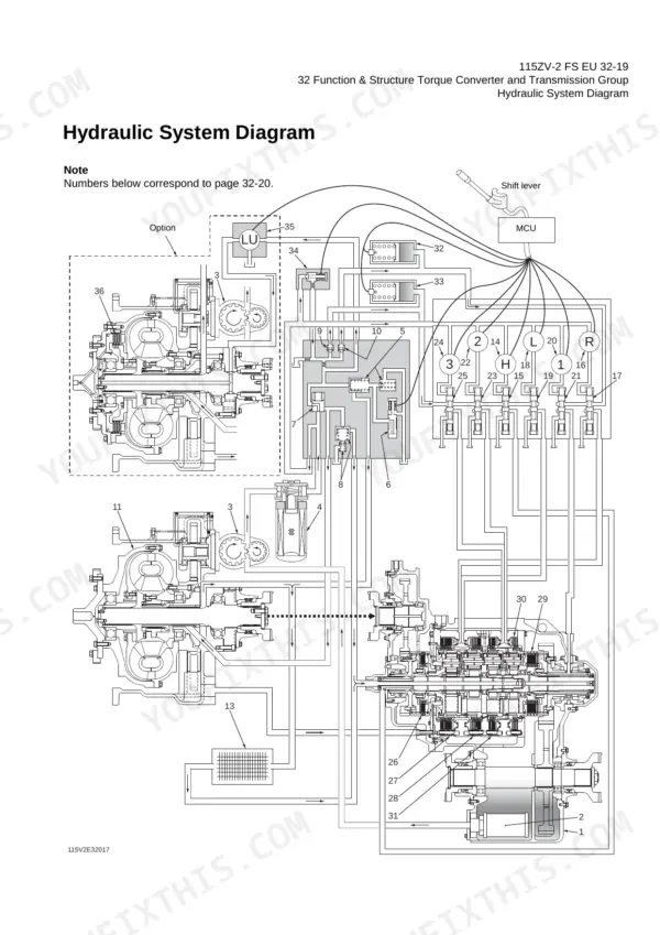
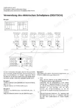
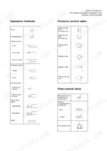
| Drawings and Diagrams | 529-701 | Axle Assembly, Torque Converter and Transmission, Hydraulic & Brake Circuit, Electrical Wiring Diagrams, Electrical Equipment Layout |
Quick Reference Specifications
| Specification | Value | Page |
|---|---|---|
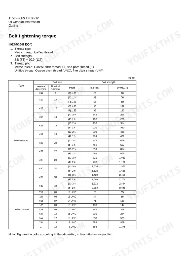
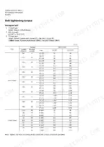
| Hexagon bolt tightening torque (M27, 8.8) | 1,030 N-m | p. 27 |
| Hexagon bolt tightening torque (M30, 8.8) | 1,422 N-m | p. 27 |
| Return filter relief valve opening pressure | 0.1±0.02 MPa (1.0±0.2 kgf/cm2) (14±2.8 psi) | p. 150 |
| Suction strainer (loading, pilot & brake) filtration area | 2,550 cm2 | p. 150 |
| Suction strainer (steering) filtration area | 2,550 cm2 | p. 150 |
| Loading line main relief pressure | 20.6±0.5 MPa (210±5 kgf/cm2) (2,986±71 psi) | p. 247 |
| Loading line overload relief pressure | 23.5±0.5 MPa (240±5 kgf/cm2) (3,413±71 psi) | p. 247 |
| Engine Oil Refill Capacity | 66 liter | p. 23 |
| Transmission Oil Refill Capacity | 90 liter | p. 23 |
| Hydraulic Tank Refill Capacity | 225 liter | p. 23 |
| Parking Brake Oil Refill Capacity | 3 liter | p. 23 |
Kawasaki 115ZV-2 Common Problems This Manual Covers
Kawasaki 115ZV-2 loading circuit with full bucket, boom and bucket cylinders moving slow and weak
Measure loading line main relief pressure following page 247; it should read 20.6 ± 0.5 MPa (2,986 ± 71 psi). Check overload relief at 23.5 ± 0.5 MPa and pilot line pressure at 3.5 MPa. If main relief reads low, adjust it at the multiple control valve before tearing into anything else.
Manual Section: Check & Adjustment Hydraulic Group p. 247Steering circuit pressure low, with the machine turning slowly and steering effort feeling heavy
Measure steering line main relief pressure following page 39 and compare it against 20.6 ± 0.5 MPa. Check the hydraulic tank level before you hook up a gauge; refill capacity is 225 liters on page 23. If relief reads low, adjust it using the steering circuit relief valve procedure starting on page 246.
Manual Section: Measurement for Performance Check p. 39Transmission engagement showing long time lag, large shock, or low travel power
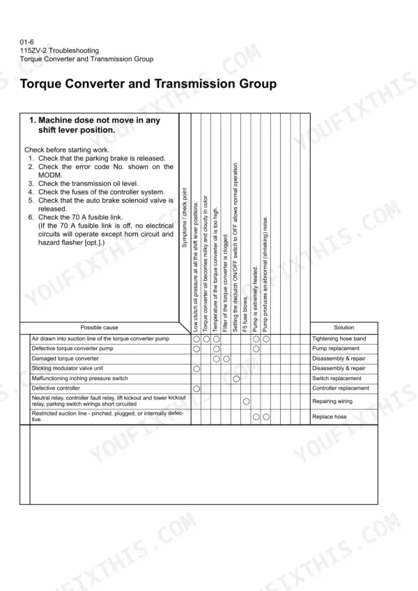
Check transmission oil level first; refill capacity is 90 liters per page 23. Then measure clutch oil pressure and time lag following page 134. If the readings are off, work through the torque converter and transmission troubleshooting charts starting, symptom by symptom, before pulling anything apart.
Manual Section: Torque Converter and Transmission Group TroubleshootingBrake warning buzzer sounding with low accumulator pressure and weak braking performance
Check unloader valve setting pressure and brake valve oil pressure following page 300. Then verify accumulator gas charging pressure against 2.94 ± 0.1 MPa as listed on page 270. Rule out the gas charge and unloader setting before you replace any brake valve components.
Manual Section: Check & Adjustment Brake Group p. 300Instrument panel going dark, with the same fuse or fusible link failing again and again
Check fuses and fusible links following page 310, then trace the failed circuit on the wiring diagram and match cable color codes as you go. Test suppression diodes on that circuit using diode check mode on page 424 before fitting another fuse.
Manual Section: Electrical Group Fundamentals p. 310Engine fault code showing on the monitor with an active error in the fault log
Check the code on the monitor, then open the MODM fault log monitor following page 372 to see stored history. Match each engine code to its description in the fault code table on page 336. For chassis codes, check the input side and output side failure listings in the chassis fault code section.
Manual Section: Engine Fault Codes (Error Codes) p. 336Frequently Asked Questions
How do I reset the replacement monitor for the Kawasaki 115ZV-2?
To reset the replacement interval, press and hold the circle (◎) button for 2 seconds or more on the replacement monitor screen to display the timer reset screen. Then, press the X-symbol (✕) button to set the standard replacement interval, which returns the display to the replacement monitor screen. p. 390
How can I clear error codes on the Kawasaki 115ZV-2?
Fault codes can be cleared by pressing and holding the X-symbol (✕) button for more than 2 seconds while in the engine fault mode or machine fault mode screens. Note that on S/N 9103 and thereafter, a password acquired from a Kawasaki Service Representative is required to perform this action. p. 394
What are the replacement specifications for the fuel filter cartridge on the Kawasaki 115ZV-2 wheel loader?
The fuel filter cartridge should be replaced every 500 operating hours. For machines from S/N 9101 and thereafter, the DCA4 coolant filter cartridge should also be replaced at this 500-hour interval. p. 20
What is the tightening torque for the M16 hexagon bolt with 10.9 (11T) strength on the Kawasaki 115ZV-2?
The tightening torque for a metric M16 hexagon bolt with 10.9 (11T) strength is 330 N-m (33.7 kgf-m) (245 lb-ft). p. 27
What is the standard engine oil capacity for the 115ZV-2?
The approximate refill capacity for the engine oil is 66 liters. p. 23
What format is this Kawasaki 115ZV-2 manual in?
One searchable PDF covering 701 pages, delivered instantly. No disc, no shipping, no waiting on the post.
Does this Kawasaki 115ZV-2 manual allow printing?
Yes. The PDF has no DRM restrictions, so print any page or section you need for your shop. Works with any standard printer.



Reviews
There are no reviews yet.