
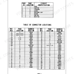
Part of the New Holland Repair Manuals.
This is the factory service manual for the New Holland Boomer 41 and Boomer 47 compact tractors, the Tier 4B Final machines rated 40.2 and 45.6 gross horsepower at 2600 RPM. It covers teardown and repair of the engine, clutch, both the gear and hydrostatic transmissions, powered front axle, rear axle and planetary final drives, PTO (mechanical and electro-hydraulic rear control), brakes, steering, wheels, cab heating and A/C, and the hood and platform sheet metal. The hydraulic chapters include the fixed displacement pump, three-point hitch control valve, and separate schematics for gear and HST models. Electrical coverage includes the starting system, fuel tank system, and full wiring diagrams as individual sheets plus composite schematic sets.
What's Inside This New Holland Boomer 41, Boomer 47 Manual
| System | Pages | Key Topics |
|---|---|---|
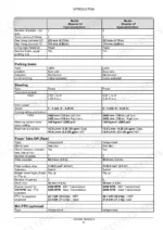
| Introduction | 1-64 | General Specifications, Engine and PTO Horsepower Ratings by Model, Fluid Capacities, Overall Dimensions, Torque Specifications for Standard Hardware |
| Engine | 65-158 | Engine and Crankcase, Air Cleaners and Lines, Fuel Filters, Engine Lubrication System, Engine Cooling System, Exhaust Gas Recirculation (EGR) |
| Clutch | 159-188 | Clutch Mechanical Release Control, Clutch and Components, Slip Clutch or Flywheel Damper |
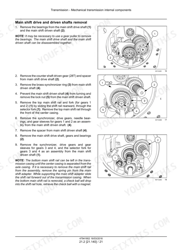
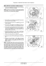
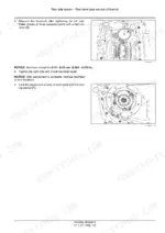
| Transmission | 189-294 | Mechanical Transmission, Mechanical Transmission Internal Components |
| Front Axle System | 295-386 | Powered Front Axle, Front Bevel Gear Set and Differential, Final Drive Hub and Steering Knuckles, Final Drives |
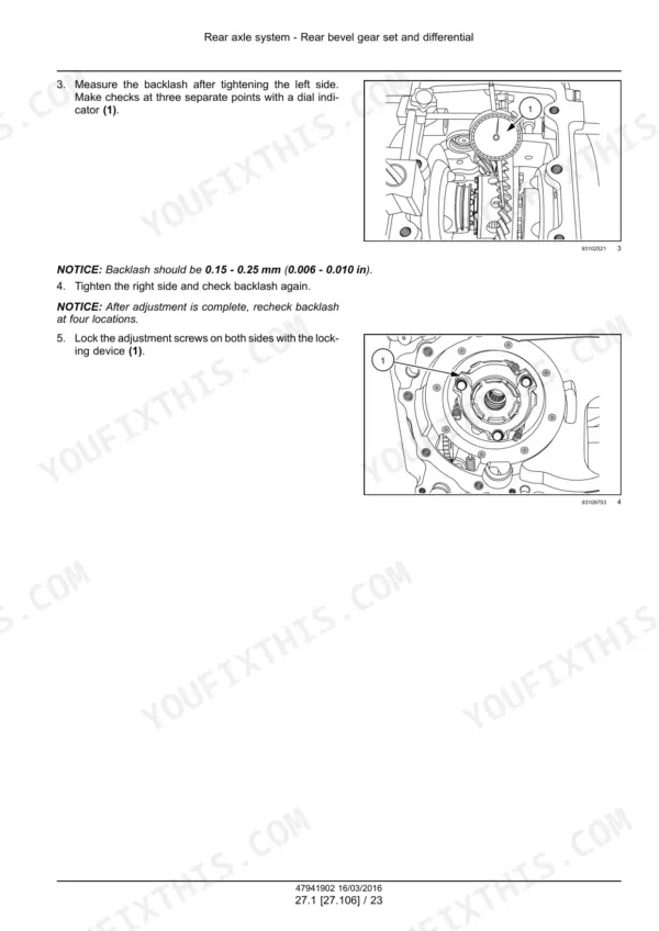
| Rear Axle System | 387-438 | Rear Bevel Gear Set and Differential, Planetary and Final Drives |
| Hydrostatic Drive | 439-530 | Transmission and Steering Hydrostatic Control, Hydrostatic Transmission, Pump and Motor Components |
| Power Take-Off (PTO) | 531-594 | Rear Mechanical Control, Rear Electro-Hydraulic Control, One-Speed Rear PTO, Central PTO |
| Brakes and Controls | 595-626 | Parking Brake or Parking Lock, Mechanical Service Brakes |
| Hydraulic Systems | 627-744 | Fixed Displacement Pump, Three-Point Hitch Control Valve, Remote Control Valves, Reservoir, Cooler, And Filters, Hydraulic Hand Control |
| Hitches, Drawbars, and Implement Couplings | 745-788 | Rear Three-Point Hitch External Controls, Rear Three-Point Hitch |
| Steering | 789-880 | Steering Control, Tie Rods, Hydraulic Control Components, Cylinders |
| Wheels | 881-898 | Front Wheels, Rear Wheels |
| Cab Climate Control | 899-1054 | Heating, Ventilation, Air Conditioning |
| Electrical Systems | 1055-1726 | Electrical System, Fuel Tank System, Engine Starting System, Battery, External Lighting, Electronic Modules, Fault Codes |
| Platform and Cab | 1727-1809 | Engine Hood and Panels, Operator Protections, Fenders and Guards, Mechanically-Adjusted Operator Seat, Cab Interior, Cab Glazing |
| Special Tool Index | 1810-1811 | |
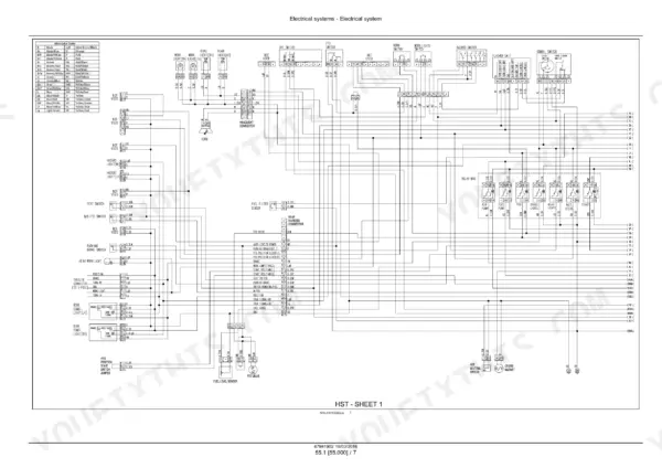
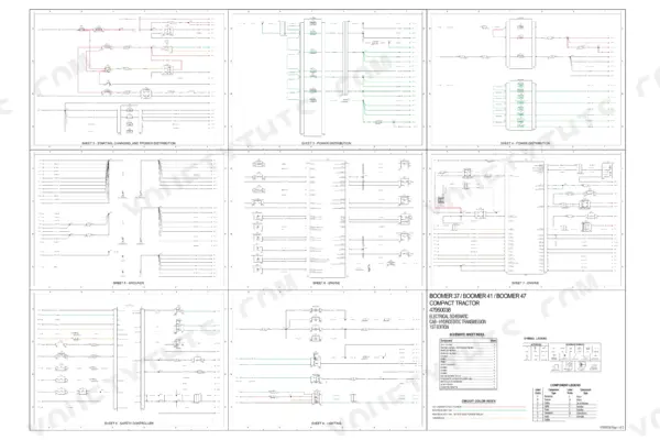
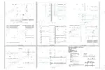
| Electrical Schematic Poster 47950038 | 1812-1813 | Electrical Schematic (Cab, Hydrostatic Transmission Configuration) - Composite Sheet Index: Starting, Charging and Power Distribution, Power Distribution, Grounds, Engine, Safety Controller, Lighting, Washer and Wiper System, Analog/Digital Instrument Cluster, Beacon and Air Conditioning, Audible Devices, Diagnostic Connector |
| Electrical Schematic Poster 47951356 | 1814-1815 | Electrical Schematic, Wiring Diagram (Configuration Variant 47951356) - Sheet Content Not Individually Rendered, Same Composite Schematic-Set Format As the Adjoining Variants |
| Electrical Schematic Poster 47708291 | 1816-1817 | Electrical Schematic (Mechanical Gear Transmission Configuration) - ECU Pinout, Engine Sensors, Glow Plug and Injector Circuits, Safety Controller, Starting/Charging Wiring, Diagnostics Connector |
Quick Reference Specifications
| Specification | Value | Page |
|---|---|---|
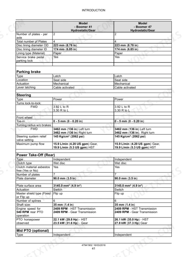
| Engine gross horsepower (Boomer 41) | 30 kW (40.2 Hp) | p. 46 |
| Engine gross horsepower (Boomer 47) | 34 kW (45.6 Hp) | p. 46 |
| PTO horsepower observed (Boomer 41, HST) | 22.1 kW (29.8 Hp) | p. 48 |
| PTO horsepower observed (Boomer 41, Gear) | 23.5 kW (31.6 Hp) | p. 48 |
| PTO horsepower observed (Boomer 47, HST) | 26.1 kW (35.0 Hp) | p. 48 |
| PTO horsepower observed (Boomer 47, Gear) | 27.8 kW (37.3 Hp) | p. 48 |
| Rated engine speed | 2600 RPM | p. 46 |
| Fuel tank capacity | 40 L (10.5 US gal) | p. 46 |
| Engine oil capacity (with filter) | 5.7 L (6.0 US qt) | p. 46 |
| Cooling system capacity | 7.5 L (2.0 US gal) | p. 46 |
| Rear axle and transmission oil capacity | 43.0 L (11.4 US gal) | p. 46 |
| Front axle oil capacity | 8.0 L (8.4 US qt) | p. 46 |
| Steering pump flow (Gear transmission) | 15.9 L/min (4.20 US gpm) | p. 48 |
| Steering pump flow (Hydrostatic transmission) | 19.9 L/min (5.3 US gpm) | p. 48 |
| Hydraulic lift system relief valve setting | 16671 kPa (2418 psi) | p. 47 |
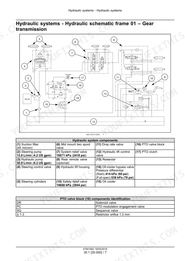
| Hydraulic pump flow, main pump (Gear transmission sheet) | 30.9 L/min (8.2 US gpm) | p. 634 |
| Overall length (FWD) | 3253 mm (128.1 in) | p. 56 |
| Wheelbase (FWD) | 1858 mm (73.2 in) | p. 56 |
| Weight with ROPS, less tires (HST FWD) | 1583 kg (3490 lb) | p. 56 |
| Weight with ROPS, less tires (Gear FWD) | 1553 kg (3424 lb) | p. 56 |
New Holland Boomer 41, Boomer 47 Common Problems This Manual Covers
Weak, jerky, or noisy hydrostatic drive after skipped fluid service
Start with the hydraulic oil and filter, since contamination is the usual killer here. Then use the Hydrostatic drive chapter to inspect the pump and motor components for scoring, and verify system pressure against the 19608 kPa (2844 psi) relief spec.
Manual Section: Hydrostatic drive - Hydrostatic transmission, Pump and motor components p. 634Engine overheating in summer work or heavy loader use
Check coolant level, fan belt tension, and airflow through the screen and radiator before condemning anything expensive. The Engine chapter covers the crankcase and the air cleaners and lines, so you can rule out a restricted intake making the engine work harder than it should.
Manual Section: Engine - Engine and crankcase, Air cleaners and lines p. 65Battery terminal corrosion, acid residue, and repeat electrical gremlins
These tractors are known for battery venting and corroded connections that show up later as random no-starts and sensor faults. Use the Electrical Systems chapter and the wiring diagrams, sold as individual sheets and composite sets, to trace the starting circuit and clean every ground and connector in the affected run.
Manual Section: Electrical Systems - Engine starting system, wiring diagrams p. 1055Tractor runs cold or takes forever to reach operating temperature
A thermostat or check-valve ball stuck open lets coolant bypass constantly, so the engine never warms up, which hurts fuel burn and cab heat. Pull and test the thermostat using the Engine chapter procedures, and check cab heater output against the Cab climate control chapter if heat is still weak.
Manual Section: Engine - Engine and crankcase p. 65Frequently Asked Questions
Does this manual cover both the gear transmission and the hydrostatic (HST) versions of the Boomer 41 and 47?
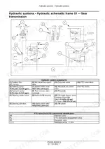
Yes, both. The Transmission chapter handles the mechanical gearbox and its internal components, and there is a separate Hydrostatic drive chapter covering the transmission and steering hydrostatic control plus pump and motor components. The hydraulic schematics are also split: frame 01 for the gear transmission and frame 02 for the hydrostatic transmission, so you follow the diagram that matches your machine. p. 634
My HST feels weak and whines after a few hundred hours. Will this manual help me sort it out?
This is the most common complaint on these tractors and it almost always traces back to neglected hydraulic oil and filter changes or contamination in the system. The Hydrostatic drive chapter walks you through the pump and motor components so you can inspect for wear, and the manual gives you the safety relief valve figure of 19608 kPa (2844 psi) to test against instead of guessing. p. 634
Are full wiring diagrams included? These are ECM tractors with glow plug relays and sensors everywhere.
Yes. The Electrical Systems chapter includes wiring diagrams both as individual sheets and as composite schematic sets, covering the engine starting system, fuel tank system, glow plug relay, injector solenoids, and the sensors on these Tier 4B Final machines. That matters because chasing a corroded connector or a dead relay without a schematic on an ECM tractor is mostly luck. p. 1812
Does it cover the three-point hitch and hydraulics, including pressure specs?
Yes. You get the fixed displacement pump and the three-point hitch control valve in the Hydraulic systems chapter, plus the external controls and hitch teardown in the Hitches chapter. The manual specifies the lift system relief valve setting at 16671 kPa (2418 psi) and, on page 48, steering pump flow of 15.9 L/min on gear models or 19.9 L/min on HST models; the main hydraulic pump is a separate item at 30.9 L/min on the gear-transmission schematic sheet, so you can test the system against real numbers. p. 634
Is this the right manual for engine work like fuel filters, air intake, and cooling problems?
Yes. The Engine chapter covers the engine and crankcase, air cleaners and lines, and fuel filters. Overheating on these tractors usually comes down to low coolant, a loose fan belt, or a plugged screen, and the flip side, an engine that runs too cool or warms up slowly, points to a thermostat stuck open. The manual gives you the procedures to check both directions. p. 65




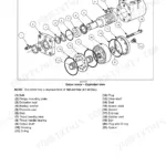
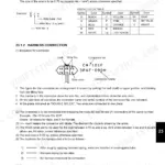


Reviews
There are no reviews yet.