
Part of the New Holland Repair Manuals.
OEM document 6-78360 NA is the factory shop manual for the EH30.B and EH35.B hydraulic excavators, delivered here as the complete New Holland EH30.B, EH35.B shop manual PDF, 764 pages cover to cover. Hydraulic circuit diagrams and electrical schematics anchor the systems section, tracing pilot control circuits and wiring runs so you can chase a fault from solenoid valve to pump. Disassembly and assembly coverage takes up the largest share of the book: attachments, the upper slewing structure, the travel system, and a full engine teardown, backed by troubleshooting tables for hydraulic, electrical, and engine faults. Check your slewing brake release pilot pressure against the 3.5 MPa (508 psi) standard, then torque the PR1 relief valve to 44 N-m (32 lb-ft). A dead excavator is a crew standing around on the clock. Print the procedure, let it get greasy at the bench, and keep the bookmarked, keyword searchable file for everything else.
What's Inside This New Holland EH30.B, EH35.B Manual
| System | Pages | Key Topics |
|---|---|---|
| General Information and Safety | 7-18 | Safety Precautions (Preparation Before Disassembling, Safety in Disassembling and Assembling, Disassembling and Assembling Hydraulic Equipment, Electrical Equipment, Hydraulic Parts, Welding Repair, Environmental Protection) |
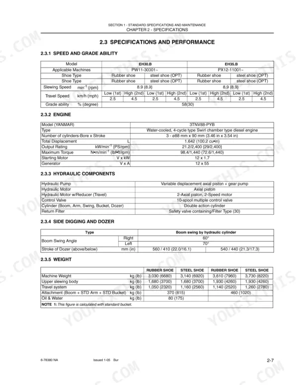
| Specifications | 19-34 | Components Name, Machine Dimensions, Specifications and Performance, Machine and Components Weights, Transportation, Type of Track Shoes, Type of Bucket, Engine Specifications |
| Attachment Dimensions | 35-60 | Boom, Arm, Bucket, Dozer, Swing |
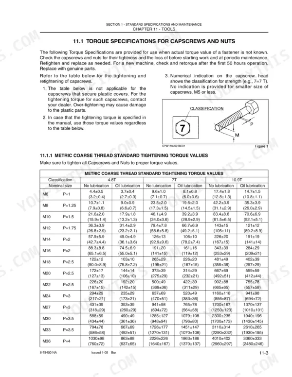
| Tools | 61-76 | Torque Specifications for Capscrews and Nuts, Screw and Tool Sizes, Torque Specifications for Joints and Hoses, Torque Specifications for Sleeve Type Tube Fittings, Plugs |
| Standard Maintenance Time Table | 77-88 | Working Standards for Time Tables, Attachment Time Tables, Canopy and Guard Time Tables, Upper Structure Time Tables, Under Carriage Time Tables |
| Maintenance Standards and Test Procedures | 89-110 | Maintenance Standards, Performance Inspection, Engine Speed, Hydraulic Oil Pressure, Travel Performance, Slew Performance |
| Hydraulic, Electrical, and Component Systems | 111-266 | Hydraulic System, Electrical System, Component System, Hydraulic Circuits, Circuit Diagrams |
| General Disassembly and Assembly | 267-490 | General Disassembly, Attachments, Upper Slewing Structure, Travel System |
| Troubleshooting | 491-538 | Hydraulic System Troubleshooting, Electrical System Troubleshooting, Engine Troubleshooting |
| Engine | 539-760 | Engine Specifications, Engine Maintenance, Engine Disassembly, Engine Inspection, Engine Reassembly |
| Electrical and Hydraulic Schematics | 761-764 | Electrical Schematics, Hydraulic Schematics |
Quick Reference Specifications
| Specification | Value | Page |
|---|---|---|
| Heavy parts hoist requirement | 20 kg [45 lbs] or more | p. 14 |
| Lock Nut (2) torque for relief valve (PR1) | 7.8 N·m (5.8 lb·ft) | p. 102 |
| Relief valve (PR1) torque | 44 N·m (32 lb·ft) | p. 102 |
| Relief valve set pressure (built in the solenoid valve 13) | 3.5 MPa (508 psi) | p. 122 |
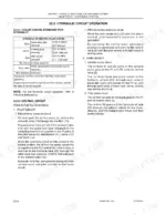
| Slewing brake release pilot primary pressure | 3.5 MPa (508 psi) | p. 124 |
| Air filter restriction switch clip installation angle | 20° downward from the level | p. 153 |
| Alternator Voltage | 12V | p. 245 |
| Air cleaner clamp trim length | 20mm | p. 153 |
| Engine stop solenoid pull coil current | 36.5 Amps | p. 259 |
| Engine stop solenoid hold coil current | 0.49 Amps | p. 259 |
| Main relief valve pressure (P1, P2) | 23.0 MPa (+0.6 / −0) | p. 94 |
| Main relief valve pressure (P3) | 20.0 MPa (+1.0 / −0) | p. 94 |
New Holland EH30.B, EH35.B Common Problems This Manual Covers
New Holland EH30.B will not travel in either direction while boom, arm and bucket still work
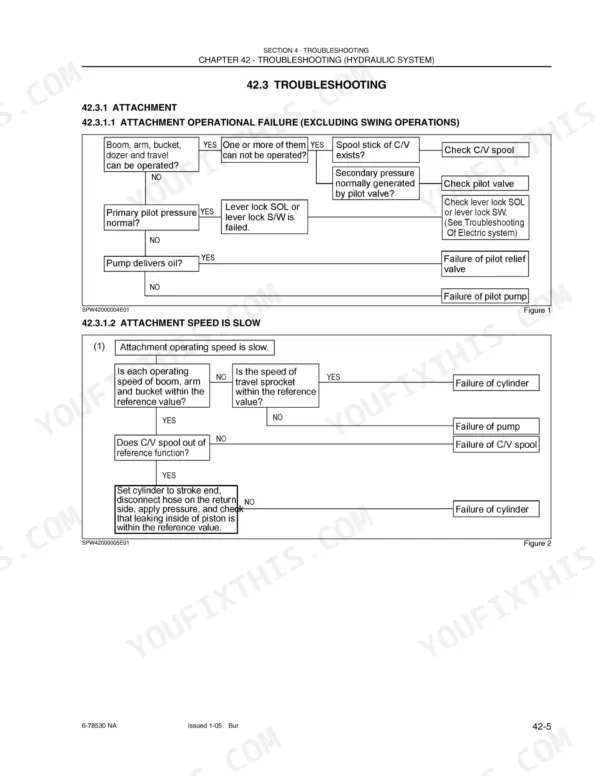
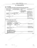
Start with the travel operational failure flowchart on page 504. Check travel pilot pressure first; it should read 35.5 kgf/cm² (505 psi) or over, and a low reading points to the pilot pump. If pressure is normal but the control valve travel spool does not move, suspect the travel pilot valve or a stuck spool. Then check the hydraulic oil filter for wear metal before condemning the travel motor or the travel reduction unit.
Manual Section: Hydraulic System Troubleshooting p. 504Engine cranks slowly in cold weather, intake heater not working, starter clicks once
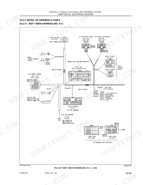
Test battery voltage under crank load first, then verify charging output; the alternator should deliver 55 A at 13.5 V, listed on page 245. Check the intake air heater for its rated DC11V supply on page 247 and confirm it draws near the 36.5 A rating when energized. Clean and tighten battery and starter cable connections before condemning the starter.
Manual Section: Electrical System Troubleshooting p. 245Hydraulics slow and noisy after machine warms up, boom and arm lose power
Check hydraulic oil level and condition first, then swap filters if service is overdue. Warm the oil and test main relief pressure against the maintenance standards on page 94; on the EH30.B, P1 and P2 should hold 23.0 MPa. Low, unstable readings point to a worn pump or suction restriction, so inspect the suction line and strainer.
Manual Section: Hydraulic System TroubleshootingRubber track keeps coming loose and jumps the front idler when turning on slopes
Measure track sag at the midpoint between rollers; on the EH30.B, set rubber track tension to 70 to 80 mm using the standards on page 95. Add grease to the idler adjuster to tighten, bleed grease to loosen. Inspect the front idler flange, rollers, and sprocket teeth for wear before blaming the adjuster.
Manual Section: Maintenance Standards and Test Procedures p. 95Attachment controls unresponsive, pilot circuit has no pressure, swing brake will not release
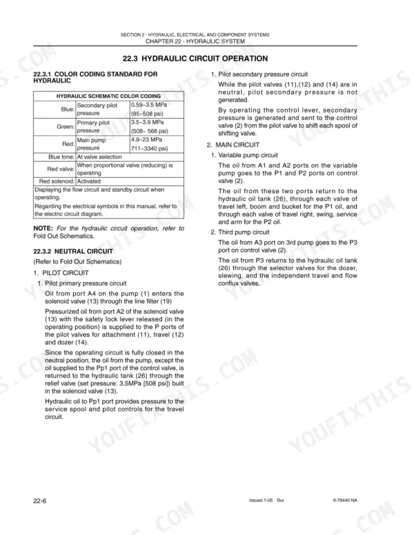
Test pilot circuit pressure first; on the EH30.B, the pilot relief valve should hold 3.5 ± 0.4 MPa per page 94. If pressure is low, trace the pilot supply through the hydraulic schematic on page 122 and check the solenoid valve for a stuck spool. Verify the pilot cutoff lever and its switch before pulling any valves.
Manual Section: Maintenance Standards and Test Procedures p. 94Frequently Asked Questions
What are the cylinder head and connecting rod bolt torques for the 3TNV82A engine in the New Holland EH30.B and EH35.B?
For the 3TNV82A engine, the cylinder head bolt tightening torque is 61.7 to 65.7 Nm (6.3 to 6.7 kgf-m). The connecting rod bolt tightening torque is 37.2 to 41.2 Nm (3.8 to 4.2 kgf-m). p. 758
What is the standard valve clearance for the 3TNV82A engine in the New Holland EH30.B and EH35.B?
The standard valve clearance for the 3TNV82A engine is 0.15 to 0.25 mm for both intake and exhaust valves. p. 747
How do I bleed air from the hydraulic cylinder after maintenance?
After maintenance, start the engine and let it idle for about 5 minutes. Extend and retract the cylinder 4 or 5 times at slow speed, moving the piston rod to 100 mm (4 in) short of its stroke end. Finally, repeat the procedure at high idle, then move the piston rod to the stroke end at low idle to open the pressure relief valve. p. 303
What is the standard compression pressure for the 3TNV82A engine in the New Holland EH30.B and EH35.B?
The standard compression pressure for the 3TNV82A engine is 3.16 +/- 0.1 MPa (31 +/- 1 kgf/cm²) at 250 min⁻¹. p. 619
What is the correct V-belt tension for the 3TNV82A engine?
For a new V-belt, the deflection should be 8 to 12 mm at position A, 5 to 8 mm at position B, and 7 to 11 mm at position C when pressed with approximately 98N (10kgf). p. 589
How is this New Holland EH30.B Shop Manual delivered?
You get a 764-page searchable PDF that downloads instantly after checkout. Open it on your laptop, tablet, or phone, and bring it right to the shop floor.
Does this New Holland EH30.B manual allow printing?
Yes, print as many copies as you want, and there are no restrictions. Many mechanics print the section they need and bring it to the shop floor.






Reviews
There are no reviews yet.