

Part of the New Holland Repair Manuals.
Electrical systems and fault codes make up the largest part of this New Holland CR6.80, CR6.90, CR7.90, CR8.90 and CR9.90 Tier 4B manual. It covers the ATC, engine ECU, UCM1, UCM2, ACM, LCP and UCM3 modules, with connector pin and wire checks.
The rest of the book covers the Cursor 9, 11 and 13 engines with SCR, the main gearbox and clutches, hydrostatic drive, axles, tracks, rotors, cleaning, unloading and the cab. It is part number 47865347, 1st edition English, April 2015, for North America.
The book is laid out by system, and the fault codes are grouped by module. A code on the display leads to its module chapter.
What's Inside This New Holland CR6.80–CR9.90 Manual
| System | Pages | Key Topics |
|---|---|---|
| Introduction and Specifications | 1-41 | Foreword, Safety Rules, Assembly Torques, General Specifications, Dimensions, Product Identification |
| Engine | 42-203 | Engine and Crankcase, Air Cleaners, Lubrication, Aftercooler, Cooling System, Fan Drive, Rotary Screen, SCR Exhaust Treatment |
| Main Gearbox and Drive | 204-273 | Main Gearbox, Main Clutch, Unload Clutch, Clutch-Pack Shimming, Gearbox Removal and Assembly |
| Transmission | 274-361 | Mechanical Transmission, External Controls, Drive Shaft, Driven Shaft, Internal Gears, Differential |
| Front and Rear Axle Systems | 362-485 | Powered Front Axle, Torsion Bar, Final Drives, Drive Hubs, Powered Rear Axle, Steering Knuckles |
| Hydrostatic Drive | 486-581 | Hydrostatic Control, Two-Speed Assembly, Hydrostatic Transmission, Reservoir and Cooler, Pump and Motor, Troubleshooting |
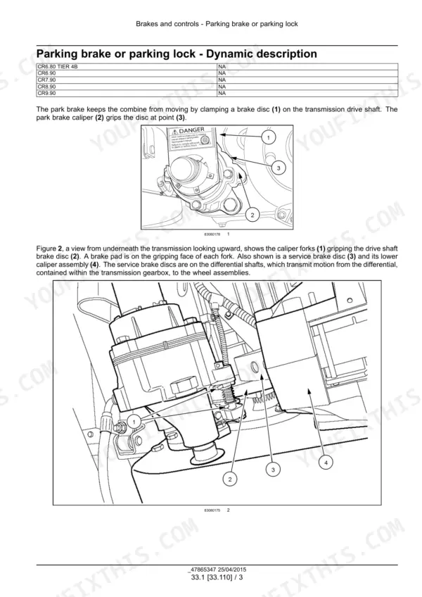
| Brakes and Controls | 582-627 | Parking Brake, Brake Control Valve, Caliper and Disks, Hydraulic Service Brakes, Brake Bleeding |
| Hydraulic Systems | 628-859 | Variable-Displacement Pump, Auxiliary Pump, Reservoir and Filters, Main Control Valve, Header Height and Leveling, Unloading, Reel and Reverser Circuits |
| Pneumatic System and Steering | 860-915 | Pneumatic System, Steering Control, Steering Pump, Steering Cylinders, Autoguidance |
| Tracks and Track Suspension | 916-1089 | Tracks, Track Frame, Driving Wheels, Track Tension Units, Track Rollers, Hub Bearings and Seals |
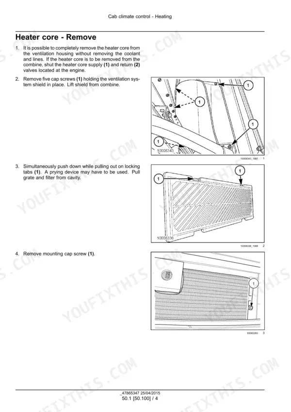
| Cab Climate Control | 1090-1165 | Heating, Ventilation, Air Conditioning, Compressor, Refrigerant Service |
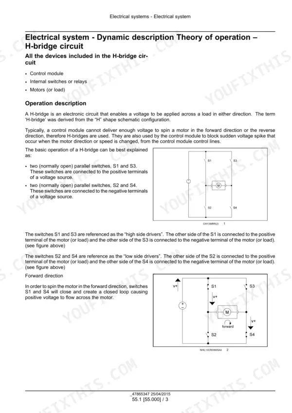
| Electrical Systems - Harnesses and Schematics | 1166-2308 | Electrical System Operation, HVAC Control, Wiring Schematics, Harness Routing, Connector Pinouts, Fuses and Relays |
| Electrical Systems - Machine Controls | 2309-2500 | Starting, Alternator and Battery, Instruments, Feeding and Cleaning Controls, Ground Speed, Electronic Modules, Header and Reel Controls, Precision Farming, SCR |
| Fault Codes - ATC and Engine Controller | 2501-3313 | Cab Temperature Sensors, HVAC Pressure Switches, Battery Voltage, Coolant and Oil Sensors, Rail Pressure, Turbocharger, DEF and NOx |
| Fault Codes - UCM1 | 3314-4304 | Grain Tank Cover Sensors, Hydraulic Reservoir Sensors, Feeder Position, Feeder Reverser, Circuit Tests |
| Fault Codes - UCM2, ACM, LCP and UCM3 | 4305-5459 | Feedrate Inclination, Steering and Navigation, Console Switches, Header Controls, Lighting, Track Sensors and Valves |
| Product Feeding and Threshing | 5460-5787 | Feed Chains and Rolls, Feeder Housing, Stone Trap, Feeder Drive, Concaves, Rotor Variator, Rotors, Rotor Housing |
| Separation and Residue Handling | 5788-6007 | Discharge Beater, Rotary Separator, Straw Chopper, Chaff Spreader, Opti-Spread System |
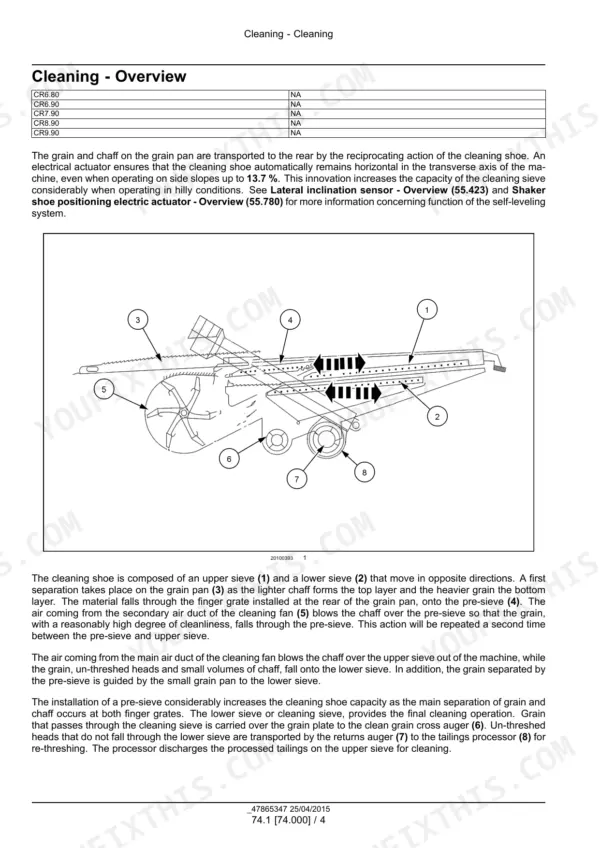
| Cleaning and Crop Storage / Unloading | 6008-6451 | Self-Leveling Sieves, Cleaning Drive, Grain Pan, Cleaning Fan, Tailings Return, Grain Elevator and Tank, Unloading Augers |
| Platform, Cab, Bodywork and Decals | 6452-6570 | Engine Hood and Panels, Shields, Footboards, Operator Seat, Cab, Special Tool Index |
| Schematic Posters | 6571-6590 | Electrical Schematic Posters 47798702 and 48193219, Hydraulic / Hydrostatic Schematic Poster 47798703 |
Quick Reference Specifications
| Specification | Value | Page |
|---|---|---|
| Gross power at 2100 RPM (CR6.80, FPT Cursor 9) | 245 kW (333 Hp) | p. 32 |
| Gross power at 2100 RPM (CR6.90, FPT Cursor 9) | 265 kW (360 Hp) | p. 32 |
| Gross power at 2100 RPM (CR7.90, FPT Cursor 9) | 300 kW (408 Hp) | p. 32 |
| Gross power at 2100 RPM (CR8.90, FPT Cursor 11) | 345 kW (469 Hp) | p. 32 |
| Gross power at 2100 RPM (CR9.90, FPT Cursor 13) | 390 kW (530 Hp) | p. 32 |
| Engine oil capacity (Cursor 9: CR6.80, CR6.90, CR7.90) | 25.0 l (6.6 US gal) | p. 82 |
| Engine oil capacity (Cursor 13: CR9.90) | 31.0 l (8.2 US gal) | p. 82 |
| Coolant capacity (CR6.80, CR6.90, CR7.90) | 50 l (13.2 US gal) | p. 101 |
| Coolant capacity (CR8.90) | 58 l (15.3 US gal) | p. 101 |
| Coolant capacity (CR9.90) | 62 l (16.4 US gal) | p. 101 |
| Fuel tank (CR6.80, CR6.90, CR7.90) | 750 l (200 US gal) | p. 32 |
| Fuel tank (CR8.90, CR9.90) | 1300 L (343.4 US gal) | p. 32 |
| Diesel Exhaust Fluid (DEF)/AdBlue tank | 145 L (38.3 US gal) | p. 32 |
| Rotor diameter (CR6.80, CR6.90, CR7.90) | 432 mm (17 in) | p. 28 |
| Rotor diameter (CR8.90, CR9.90) | 559 mm (22 in) | p. 28 |
| Cleaning fan speed | 200 - 1100 RPM | p. 31 |
| Final drive oil capacity (bull gear type 11:111, CR6.80, CR6.90, CR7.90) | 7.85 l (2.07 US gal) | p. 386 |
| Main hydraulic system maximum pressure | 210 bar ( 3046 psi) | p. 631 |
| Maximum steering pressure (priority valve) | 185 bar (2682 psi) | p. 631 |
| Torsion bar M30 nut torque | 400 - 475 Nm (295 - 350 lb ft) | p. 366 |
New Holland CR6.80–CR9.90 Common Problems This Manual Covers
DTC 1161 - Battery voltage is higher than expected
The DTC 1161 procedure in the Fault Codes (DTC) chapter checks the charging system at step 3. If the charging system is not working properly, the book says to repair it as necessary. The alternator and battery procedures are in the Electrical Systems section.
Manual Section: Electrical systems - FAULT CODES p. 2575E0001-05 - Grain Tank Covers Closed Sensor, line disconnected
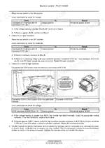
In the UCM1 fault codes, step 3 is done with the key OFF and the CM harness disconnected from the UCM. Check continuity between connector X-191 pin 2 and X-001C1B pin 16. No continuity means wire 004 yellow between those pins is faulty. Locate the faulty wiring and repair it.
Manual Section: Electrical systems - FAULT CODES p. 3319Machine will not operate in either direction
The troubleshooting chart in the Hydrostatic Drive section lists a control cable that is not connected as the cause. The printed correction is to connect the control cable. The same section covers hydrostatic control, the two-speed assembly, and the pump and motor.
Manual Section: Hydrostatic transmission - Troubleshooting p. 529Hydrostatic oil temperature too high
The hydrostatic transmission troubleshooting chart lists low oil level and a blocked oil cooler as causes of high oil temperature. The printed correction is to clean or replace the cooler as required. The reservoir and cooler are covered in the Hydrostatic Drive section of the book.
Manual Section: Hydrostatic transmission - Troubleshooting p. 529Frequently Asked Questions
Which combines does the New Holland CR6.80 - CR9.90 service manual cover?
It covers the CR6.80, CR6.90, CR7.90, CR8.90 and CR9.90 twin-rotor combines, all Tier 4B (final) for North America. The part number is 47865347, 1st edition English, April 2015. The book does not print a serial range that applies to the whole manual. Electrical poster 48193219 applies to PIN YHG120001 and above. p. 1
Which engines and power ratings does the manual list for each model?
The CR6.80, CR6.90 and CR7.90 run the FPT Cursor 9, the CR8.90 the Cursor 11, and the CR9.90 the Cursor 13. Gross power at 2100 RPM is 245 kW (333 Hp) for the CR6.80, 265 kW (360 Hp) for the CR6.90 and 300 kW (408 Hp) for the CR7.90. The CR8.90 makes 345 kW (469 Hp) and the CR9.90 makes 390 kW (530 Hp). p. 32
How much engine oil and coolant does the CR9.90 take?
The Cursor 13 in the CR9.90 takes 31.0 l (8.2 US gal) of engine oil. Coolant capacity for the CR9.90 is 62 l (16.4 US gal). For comparison, the Cursor 9 machines take 25.0 l (6.6 US gal) of oil and 50 l (13.2 US gal) of coolant. p. 82
Does the rotor diameter differ between the models?
Yes. The CR6.80, CR6.90 and CR7.90 rotors are 432 mm (17 in) in diameter, and the CR8.90 and CR9.90 rotors are 559 mm (22 in). p. 28
Does the manual include wiring diagrams, hydraulic schematics and fault codes?
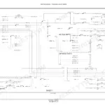
Yes. The Harnesses and connectors section carries the electrical schematic sheets, from sheet 01 power and starting to sheets 91-92 for the CAN bus. Hydraulic schemas sit in Hydraulic systems. The book ends with electrical schematic posters 47798702 and 48193219 and hydraulic / hydrostatic poster 47798703. The DTC chapter covers the ATC, engine ECU, UCM, ACM and LCP modules. p. 6571





Reviews
There are no reviews yet.