
![New Holland G110.2 G110.2 6WD Tier 2 Repair Manual [Grader]](https://youfixthis.com/wp-content/uploads/2012/02/Manual_Download-300x300.jpg)
Part of the New Holland Repair Manuals.
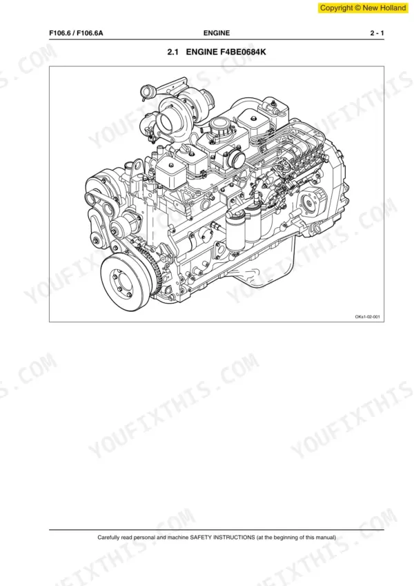
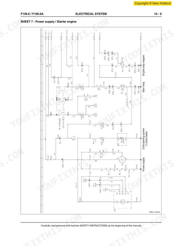
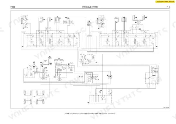
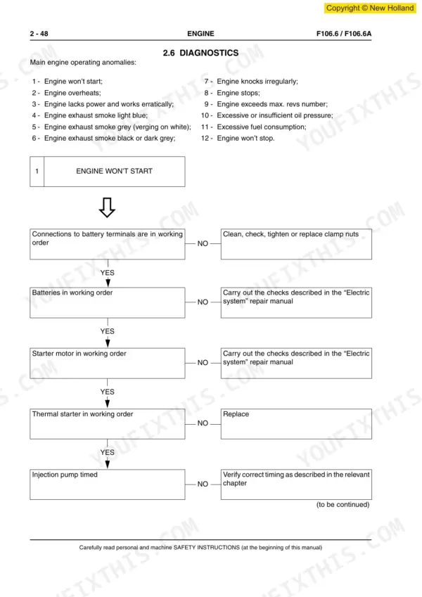
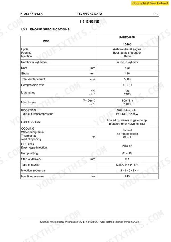
This 579-page New Holland F106.6 Grader Workshop Manual (OEM #604.13.567) covers the F106.6 and F106.6A down to the bolt, from the F4BE0684K engine through the tandem rear axle. You get complete wiring diagrams for the Can-Bus system, hydraulic schematics covering the blade and ripper circuits, and a full troubleshooting section for the ZF transmission and brake system. Inside: rear axle and front axle disassembly procedures, steering component breakdowns, and operator's cab servicing for the heating and air conditioning systems. Set front and rear axle wheel nut torque to the values specified in Section 4 and 5, and reset hydraulic pressure using the exact procedure in Section 7, not a guess carried over from another grader. Oil-damaged wiring harnesses stop being a mystery once you can trace the actual circuit. Bookmarked by section, so you open straight to Hydraulic System or Electrical System on your tablet and start diagnosing right there in the cab.
What's Inside This New Holland F106.6, F106.6A Manual
| System | Pages | Key Topics |
|---|---|---|
| Safety Instructions | 7-44 | Fundamental Safety Instructions, Warning and Instruction Signs, Operation, Inspection and Servicing |
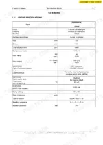
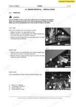
| Engine | 59-124 | Engine F4BE0684K, Engine Removal - Installation, General Remarks, Injection Assembly, Recharge and Start-Up, Diagnostics |
| Transmission | 125-174 | General Description, Operation, Zf Diagnostic System |
| Rear Axle | 175-270 | General Information, General Specifications, Tandem Axle Removal - Installation, Disassembly and Assembly Operations, Troubleshooting |
| Front Axle | 271-354 | General Information, General Specifications, Front Wheel Drive System (Only for F106.6A), Front Axle Removal - Installation, Disassembly and Assembly Operations |
| Attachment | 355-390 | Central Attachment, Front Attachment (Opt) (Blade or Ripper), Rear Attachment (Opt) (Ripper), Front Frame |
| Hydraulic System | 391-460 | General, Hydraulic Diagrams, Main Functions, Main Components, Maintenance, Overhaul |
| Brake System | 461-480 | System Operation, Brake System Components - Operation Description, Troubleshooting |
| Steering System | 481-494 | System Operation, Steering System Components - Operation Description |
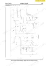
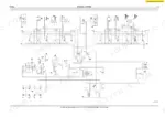
| Electrical System | 495-556 | Wiring Diagram, Can-Bus System |
| Operator's Cab | 557-579 | Operator's Cab Components, Ventilation and Heating (Generalities) |
Quick Reference Specifications
| Specification | Value | Page |
|---|---|---|
| Hydraulic System | SECTION 7 | p. 3 |
| Attachment | SECTION 6 | p. 3 |
| ELECTRICAL SYSTEM | SECTION 10 | p. 3 |
| FRONT AXLE | SECTION 5 | p. 3 |
| REAR AXLE | SECTION 4 | p. 3 |
| ENGINE | SECTION 2 | p. 3 |
| Main pressure valve | 16 + 2.5 bar | p. 138 |
| Possible error codes: 24 V voltage interrupted | 24 V | p. 140 |
New Holland F106.6, F106.6A Common Problems This Manual Covers
New Holland F106.6 grader hydraulic system won't hold blade position on downhill grades, blade creeps down under load
Depressurize the system first following the residual pressure reduction procedure on page 33. Check the pressure relief valve setting on page 424; it should read 215 bar. Inspect the screw plug torque on page 419, spec is 30 Nm. Replace worn valve seals if pressure bleeds down after shutoff.
Manual Section: Hydraulic System p. 424Electrical system shorts out and wiring harness fails after oil splashes near ignition components
Inspect the wiring harness for oil contamination near the ignition circuit. Check fuse F1 for the central electronic unit; it should be rated at 15 A per page 503. Replace any fuse with the current rating specified on page 14, never a higher amperage. Clean and dry all affected connectors before reconnecting power.
Manual Section: Electrical System p. 503Engine won't reach full power or RPM until the machine warms to operating temperature
Check the engine troubleshooting procedures starting for lack-of-power conditions. Verify coolant and oil temperature reach operating range before demanding full load, per the performance note on page 25. Never force full throttle on a cold engine; let it idle until warm. Test injection timing if power stays low after warm-up.
Manual Section: EngineWheel nuts loosen repeatedly on the rear axle despite routine checks during operation
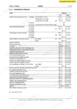
Always tighten wheel nuts with a calibrated torque wrench, never an impact gun alone, per the procedure on page 39. Torque rear axle wheel nuts to 650 Nm as specified on page 193. Recheck torque after several hours of operation once the machine has been run under load. Replace any nuts or lock assemblies showing thread damage.
Manual Section: Rear Axle p. 193Blade elevation control lags or won't respond, bucket lift feels sluggish under load
Check hydraulic pressure at the relief valve, it should hold at 215 bar per page 424. Depressurize the circuit using the procedure on page 33 before removing the elevation servo valve for inspection. Clean the valve spool and seat of contamination, then reassemble with new seals. Bleed the circuit fully before testing lift response.
Manual Section: AttachmentFrequently Asked Questions
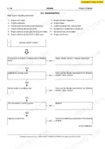
How can I reset the error code on a New Holland F106.6 grader?
To reset the error code, connect a Lap-Top with the “Diagnosis” plug of the cable harness. Then, select the “Cancel Fault storage” group under “Diagnosis” and acknowledge with “YES”. p. 155
What are the torque specifications for the engine bolts on a New Holland F106.6A?
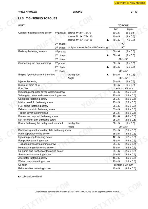
The tightening torques for cylinder head fastening screws vary by length: M12x1.75x70 screws require 50 ± 5 Nm, M12x1.75x140 screws require 40 ± 5 Nm, and M12x1.75x180 screws require 70 ± 5 Nm. For the latter two, there are additional 90° turns in the 2nd and 3rd phases. p. 73
How do I reset the hydraulic system pressure on a New Holland F106.6 grader?
To reset the hydraulic system pressure, ensure the system is depressurized before any intervention. Residual pressure reduces gradually after stopping the machine, but for immediate intervention, the system must be depressurized as described in the Hydraulic System section. p. 33
What are the torque specifications for the transmission mounting bolts on a New Holland F106.6A?
The outer screws securing the transmission group to the engine should be tightened to a final torque of 44 Nm. The four inner screws securing the flywheel to the torque converter should also be tightened to 44 Nm. p. 79
How will I receive this New Holland F106.6 Workshop Manual?
You get a 579-page searchable PDF that downloads instantly after checkout. Open it on your laptop, tablet, or phone, and bring it right to the shop floor.
Does this New Holland F106.6 manual allow printing?
No restrictions at all. Print individual pages, full chapters, or the entire manual. The PDF is completely unlocked.
Does this New Holland F106.6 manual show the machine's wiring?
Yes, full electrical schematics are included with wire colors, connector locations, and circuit descriptions.







Reviews
There are no reviews yet.