
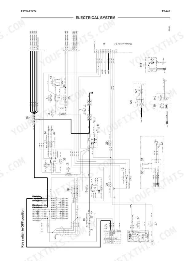
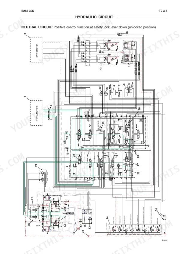
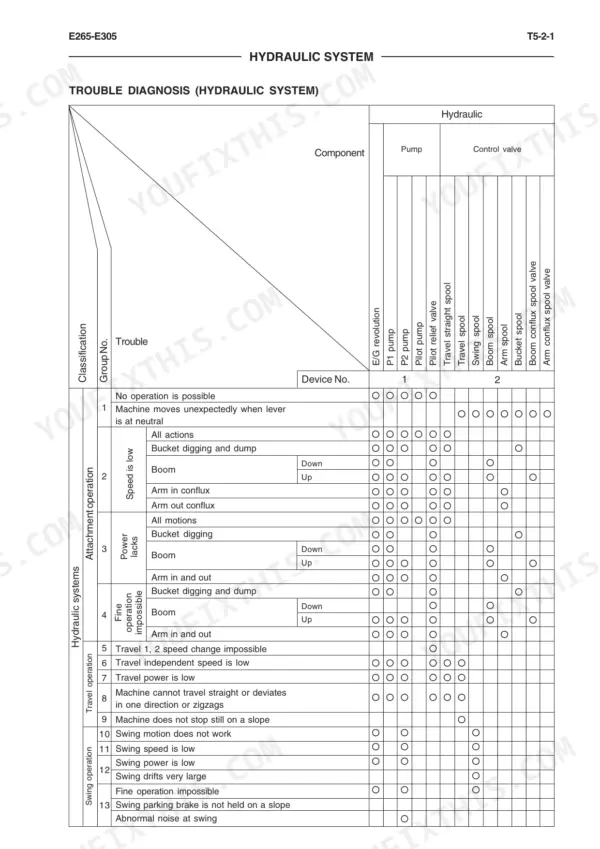
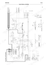
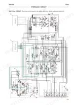
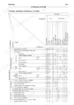
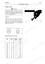
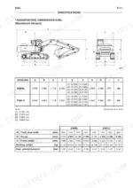
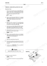
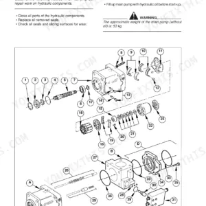
A dead Mechatro fault code at 6 a.m. with a crew waiting is exactly the problem this book was written for: the 864-page New Holland Kobelco E265, E305 workshop manual PDF, factory document 604.13.674, covering both hydraulic excavators from safety plates to final drive rebuild. Wiring diagrams trace every harness through the Mechatro controller, and hydraulic schematics map the pilot circuit, control valve, and swing and travel motors alongside troubleshooting trees keyed to self-diagnosis failure codes. Repair chapters walk the undercarriage piece by piece: swing bearing, track adjuster, front idler, rollers, and track chain. When you chase a weak function, confirm the return and make-up circuit holds 249 to 490 kPa, then torque the PF1 port to 200 to 250 Nm on reassembly. Nobody around has wrenched a Mechatro system before? This text-searchable PDF answers the questions you would otherwise ask no one, so the diagnosis lands right the first time.
What's Inside This Manual
| System | Pages | Key Topics |
|---|---|---|
| Introduction | 3-4 | To the Reader, Workshop Manual Composition, Page Numbering, Symbols, Units Used |
| Safety Precautions | 7-44 | Generalities, Starting, Operating, Maintenance, Transfers and Transportation, Electrical System, Hydraulic System |
| Safety Plates | 45-50 | Attachment Operating Range, Track Adjuster, Counterweight, Read-Your-Manual, Engine Hood, Controls Lock/Unlock |
| Operational Principle | 53-184 | General (Specifications, Component Layout), System (Mechatro Control System, Mechatro Controller, Hydraulic System, Electrical System) |
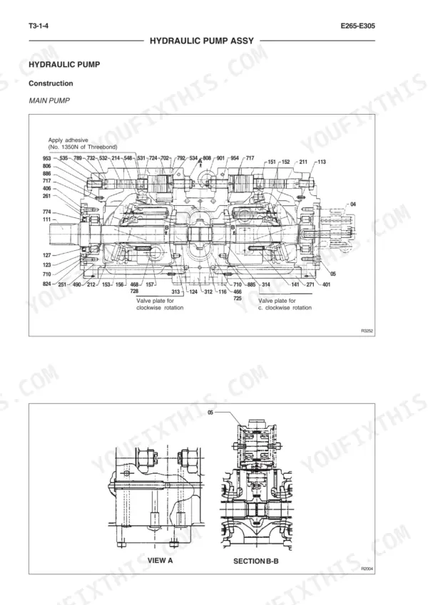
| Operational Principle - Component Operation | 185-328 | Hydraulic Pump Assy, Pilot Valve, Control Valve, Swing Device, Travel Device, Swivel Joint, Cylinders, Air Conditioner |
| Operational Performance Test | 329-362 | Standard Performances, Test Procedures, Mechatro Controller Adjustment, Engine Control Input/Output |
| Troubleshooting | 363-458 | Mechatro Control, Hydraulic System, Electrical System, Engine, Self-Diagnosis Function, Failure Codes |
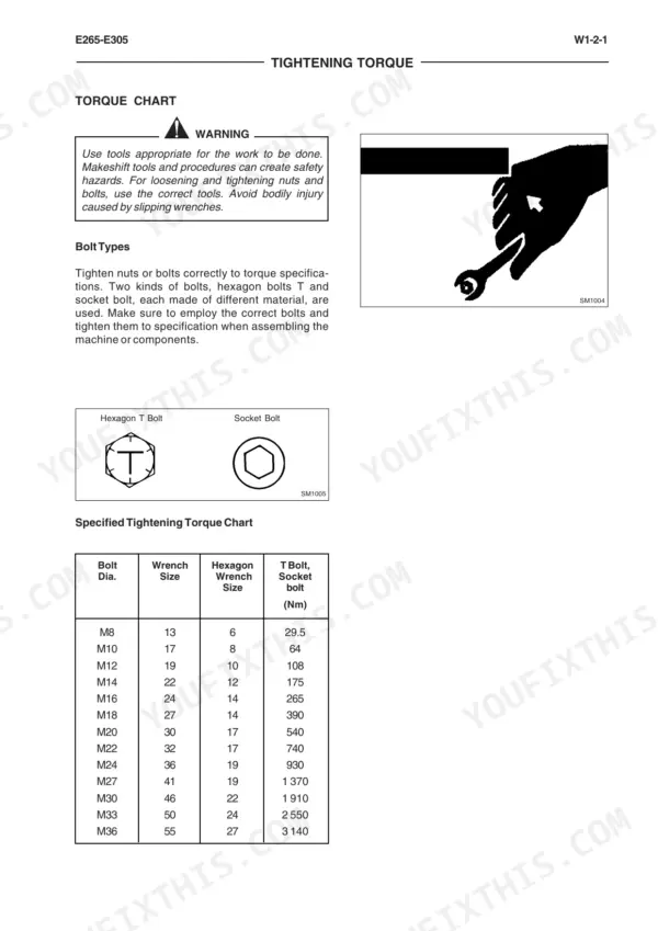
| Repair Instructions - General Information | 459-480 | Precautions for Disassembly and Assembly, Tightening Torque |
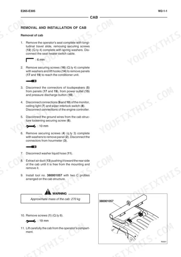
| Repair Instructions - Upperstructure | 481-558 | Upperstructure (Cab, Air Conditioner, Counterweight, Main Frame, Pump Device, Control Valve, Swing Device, Pilot Valve, Solenoid Valve Unit) |
| Repair Instructions - Undercarriage | 647-806 | Swing Bearing, Travel Device, Swivel Joint, Track Adjuster, Front Idler, Upper and Lower Roller, Tracks |
| Repair Instructions - Front Attachment | 807-858 | Front Attachment, Cylinders, Bucket Teeth |
Quick Reference Specifications
| Specification | Value | Page |
|---|---|---|
| All Models | ||
| Tightening torque for PF1 port | 200 ~ 250 Nm | p. 223 |
| Signal level for pressure sensors | 0.5~4.5V | p. 120 |
| Signal level for power source | 5V | p. 120 |
| Feed, drain, tank circuit pressure | less than 245 kPa | p. 124 |
| Return, make up circuit pressure | 249 kPa to 490 kPa | p. 124 |
| Tightening torque for PF3/4 port | 150 ~ 180 Nm | p. 223 |
| Main relief valve set pressure | 34.3 MPa at 180 L/min | p. 221 |
| E265 | ||
| Max. flow | 242x2 L/min | p. 221 |
| Main relief valve set pressure | 34.3 MPa at 180 L/min | p. 67 |
| Socket screw M12x40 torque | 108 ± 10 Nm | p. 283 |
| Relief valve torque | 375 ± 20 Nm | p. 283 |
| E305 | ||
| Main relief valve set pressure | 34.3 MPa at 180 L/min | p. 70 |


