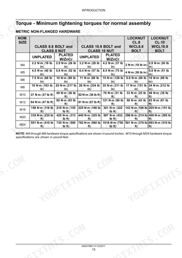
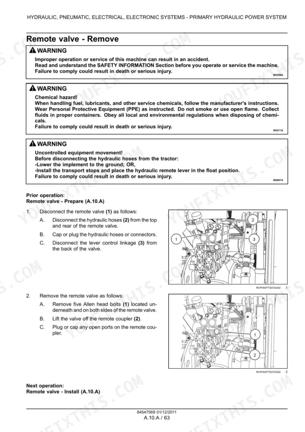
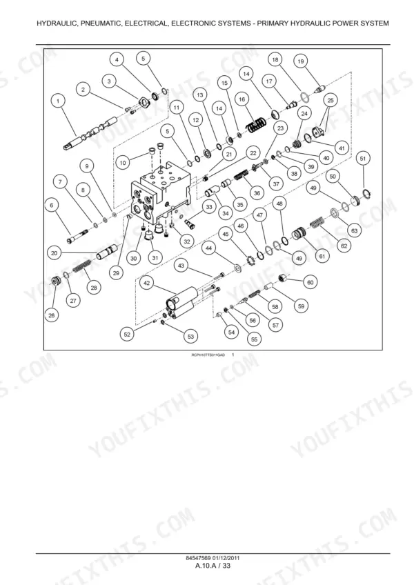
If a TS6020, TS6030 or TS6030HC lives on your place, this New Holland TS6020, TS6030, TS6030HC service manual PDF is the factory book for all three: 864 pages under OEM part 84547569. Electrical work claims the largest share, roughly a quarter of the book, with connector diagrams from X-001 through X-099 and full harness schematics frame by frame. Hydraulic schematics trace the remote valves, couplers, and steering circuits, while the drivetrain chapters walk the power coupling clutch, creeper reducers, both axles, and the rear hitch from teardown to reassembly. Set an M24 Class 10.9 flanged bolt to 1118 N·m (824 lb ft), and know an unplated M4 takes just 2.2 N·m (19 lb in). Guess a torque and you shear a stud during planting. The text layer answers keyword searches, bookmarks split every section, and the file rides wherever the tractor works.
Complete the set for your TS6020, TS6030, TS6030HC
What's Inside This Manual
| System | Pages | Key Topics |
|---|
| Introduction | 3-34 | Ecology and the Environment, International Symbols, Safety Rules |
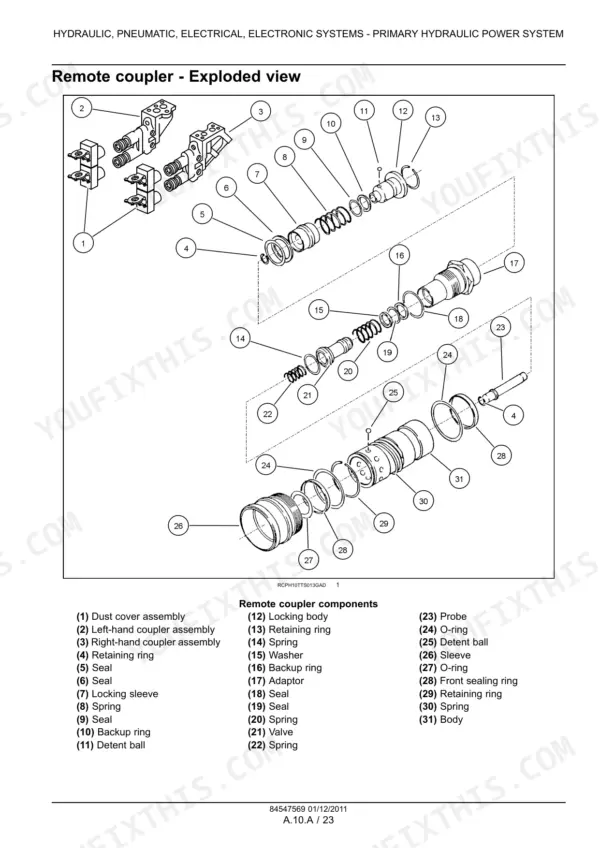
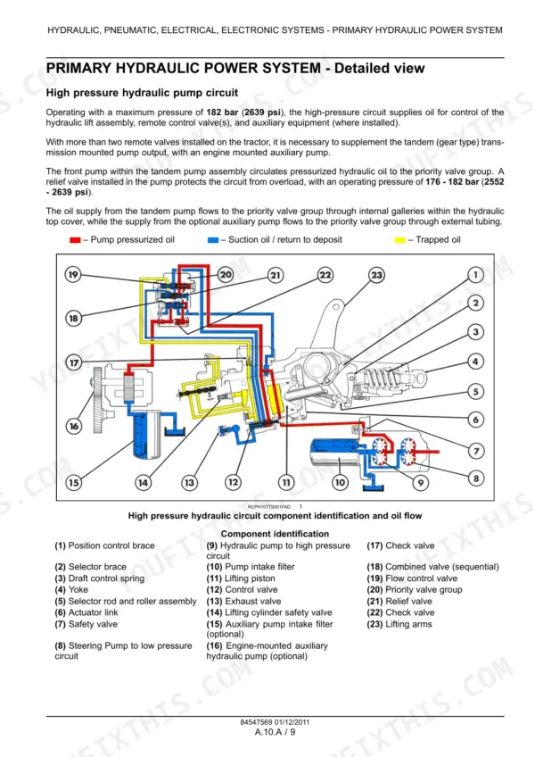
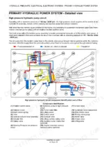
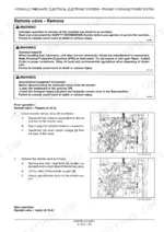
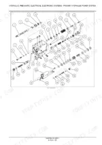
| Primary Hydraulic Power System | 35-160 | Hydraulic Pump, Remote Coupler, Remote Valve, Control Valve, Hydraulic Symbols, Hydraulic Schema |
| Electrical Power System - Connectors X-001 to X-029 | 161-242 | Connector Diagrams, Lighting, Horn, Grid Heater, Starter Solenoid, Alternator, Turn Signal, Hazard Switch |
| Electrical Power System - Connectors X-030 to X-099 | 243-306 | Buzzer, 4WD Switch, Stop Lamp Switch, Dual Power Switch, Beacon Light, Work Lamp, Radio, HVAC System |
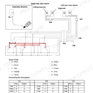
| Electrical Power System - Wiring Harness Schematics | 307-384 | Wiring Harness Schematics, Frame 01-22, Component Identification, Electrical Circuit Diagrams |
| Engine and PTO in | 385-402 | Engine |
| Transmission, Drive and PTO Out | 403-524 | Power Coupling Clutch, Transmission Mechanical, Additional Reducers Creeper |
| Axles, Brakes and Steering | 525-690 | Front Axle, Rear Axle, 2WD-4WD System Hydraulic, Steering Hydraulic, Service Brake Mechanical, Parking Brake Mechanical |
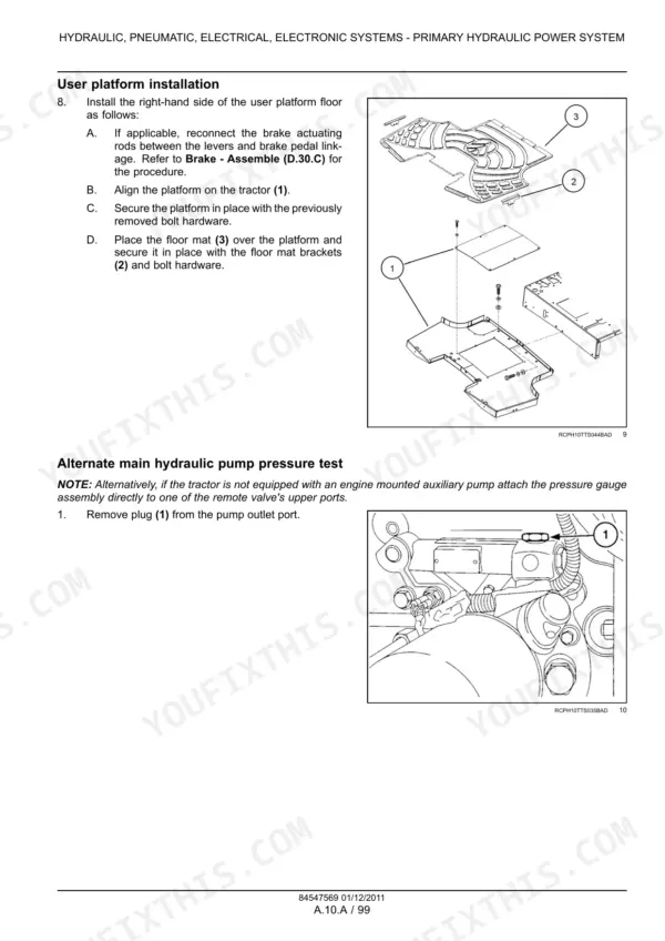
| Frame and Cab | 691-806 | User Controls and Seat Control, User Platform, Environment Control Heating, Ventilation and Air-Conditioning |
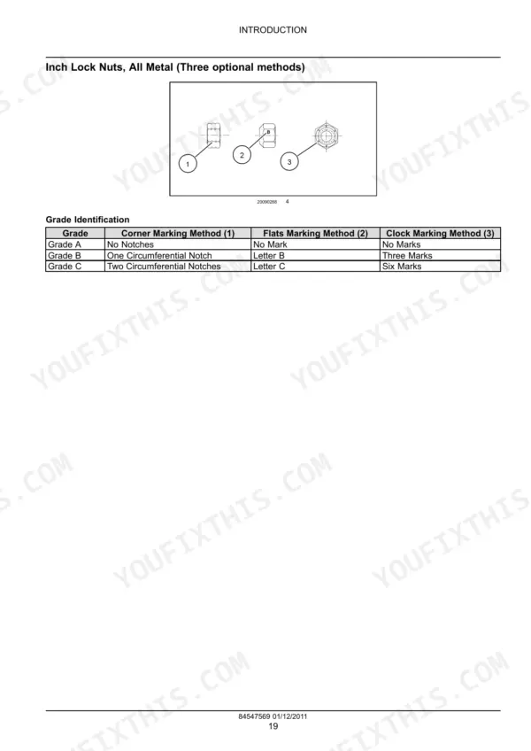
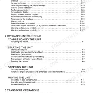
| Hitch and Working Tool | 807-864 | Hitch Rear Hitch (Foreword - Ecology and the Environment, International Symbols, Safety Rules, Safety Rules - Personal Safety, Basic Instructions - Important Notice Regarding Equipment Servicing, Torque - Minimum Tightening Torques for Normal Assembly, Torque - Standard Torque Data for Hydraulics, Basic Instructions - Chain Wear Tables - Roller Chains, Basic Instructions - Shop and Assembly, Basic Instructions - How to Use and Navigate Through This Manual) |
Quick Reference Specifications
| Specification | Value | Page |
|---|
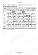
| Metric non-flanged hardware torque (M4, Class 8.8 bolt/Class 8 nut, unplated) | 2.2 N·m (19 lb in) | p. 17 |
| Metric non-flanged hardware torque (M24, Class 10.9 bolt/Class 10 nut, plated W/ZnCr) | 1016 N·m (750 lb ft) | p. 17 |
| Metric flanged hardware torque (M4, Class 8.8 bolt/Class 8 nut, unplated) | 2.4 N·m (21 lb in) | p. 18 |
| Metric flanged hardware torque (M24, Class 10.9 bolt/Class 10 nut, plated W/ZnCr) | 1118 N·m (824 lb ft) | p. 18 |
| Inch non-flanged hardware torque (1/4, SAE Grade 5 bolt and nut, unplated or plated silver) | 8 N·m (71 lb in) | p. 17 |
| Inch non-flanged hardware torque (1, SAE Grade 8 bolt and nut, plated W/ZnCr gold) | 1187 N·m (875 lb ft) | p. 19 |
| Tube nuts for 37° flared fittings torque (Size 4) | 12 - 16 N·m (9 - 12 lb ft) | p. 20 |
| Tube nuts for 37° flared fittings torque (Size 32) | 305 - 325 N·m (225 - 240 lb ft) | p. 20 |
| Main Hydraulic Pump Safety Valve Activation Pressure | 176 - 182 bar | p. 43 |
| Relief Valve Minimum Operating Pressure (Low Pressure and Lubrication Circuit) | 5.3 bar | p. 46 |
| Lubrication Circuit Relief Valve Minimum Operating Pressure | 5.3 bar | p. 134 |
| Transmission Output Shaft End Play | 0.038 - 0.086 mm | p. 428 |