Part of the New Holland Repair Manuals.
A combine that quits threshing in the second week of harvest does not wait for a dealer appointment, and this New Holland TX66, TX68 repair manual PDF exists for exactly that moment: 980 pages of factory service data, OEM ID 86603389, also covering the TX62, TX64, TX65 and TX67. Electrical circuit diagrams take up more of the book than any other section, tracing starter, header lift and straw chopper engagement wiring pin by pin, backed by full hydraulic and hydrostatic schematics. Troubleshooting charts walk you from a hydrostatic drive fault or a header height complaint to the cause, and InfoView error codes plus calibration procedures close out the book. Set the variator belt tension spring at 66 mm and pull 440 Nm for the final drive bolts from the same tables your dealer uses. Guess a torque on a final drive and you shear a hub mid-field. Bookmarked and text searchable, the PDF rides in the cab or the shop, wherever the machine happens to stop.
Other edition of this manual
What's Inside This Repair Manual
| System | Pages | Key Topics |
|---|---|---|
| Introduction | 5-18 | Machine Serial Numbers, Tightening Torques |
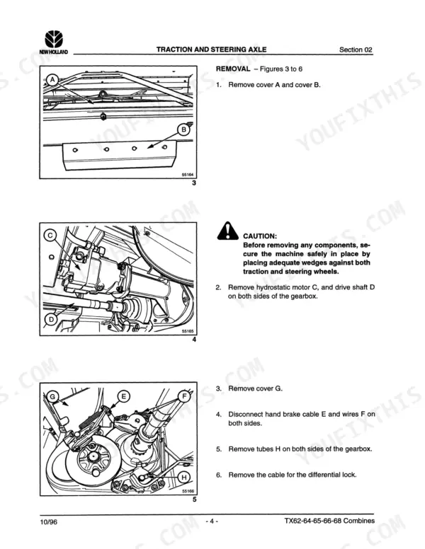
| Traction and Steering Axle | 19-74 | Traction Gearbox, Brakes, Final Drives |
| Grain Header | 75-94 | Reel, Knife and Wobble Box, Feed Auger |
| Straw Elevator | 95-114 | Straw Elevator Chain, Upper Shaft, Bottom Shaft |
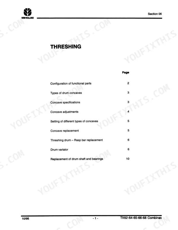
| Threshing | 115-126 | Concave Adjustments, Threshing Drum, Drum Variator |
| Separation | 127-148 | Concaves, Intermediate Shaft, Beater Shaft |
| Cleaning | 149-180 | Cleaning Fan and Variator, Cleaning Shoe Drive, Shaker Shoe |
| Grain Storage | 181-202 | Unloading System, Clean Grain Transport System, Return System |
| Straw Chopper/Chaff Spreader | 203-224 | Straw Chopper, Rotor Bearings, Straw Chopper Clutch |
| Engines | 225-234 | Fuel Injection Pump, Fuel Injectors, Cooling System |
| Air Conditioning | 235-246 | Air Conditioning Circuit, Ventilation Unit, Compressor Clutch Replacement |
| Hydraulic System | 247-312 | Hydraulic Pump, Header Height Control Valve, Hydraulic Cylinders |
| Hydrostatic System | 313-400 | Hydrostatic Pump, Hydrostatic Motor |
| Electrical System General Information | 401-420 | Wiring Identification, Color Codes, Relays, Connector Pinouts |
| Electrical Symbols and Diagrams | 421-446 | Electrical Symbols, Wiring Diagrams, Connector Diagrams, Component Identification |
| Electrical Circuit Diagrams | 447-716 | Starter Circuits, Hydrostatic System, Engine Throttle, Header Lift Control, Straw Chopper Engagement |
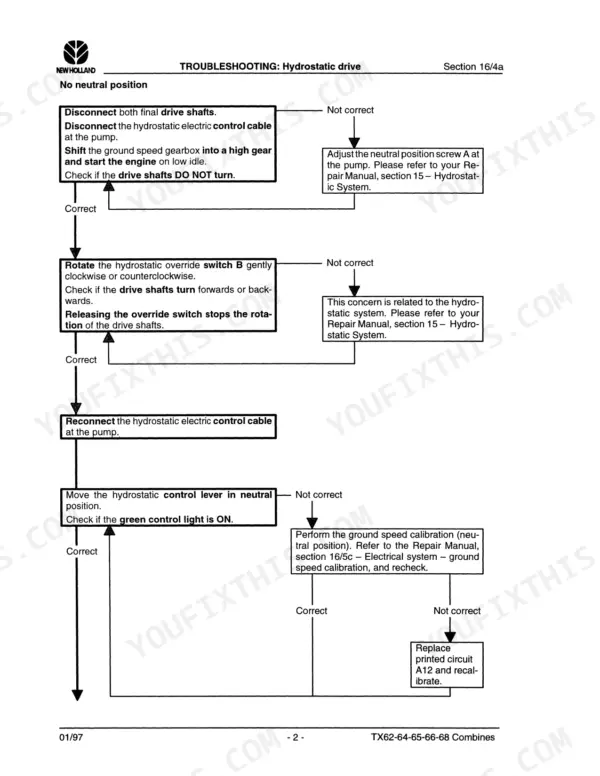
| Troubleshooting and Diagnostics | 717-888 | Hydrostatic Drive, Throttle Control, Straw Chopper Engagement, Header Lift Control, Lateral Float Control |
| Self-Diagnostic Error Reports | 889-932 | InfoView Monitor Errors, Header Height Control Errors, Remote Gearshift Errors, Sensor Error Codes |
| Calibration Procedures | 933-980 | InfoView Monitor Calibration, Header Calibration, Ground Speed Calibration, Returns Constant Calibration |
Quick Reference Specifications
| Specification | Value | Page |
|---|---|---|
| Bolts G (final drive) | 440 Nm | p. 46 |
| Torque E | 100 Nm | p. 46 |
| Torque D | 80 Nm | p. 46 |
| Sprockets B and C mounting hardware torque | 100 Nm | p. 79 |
| Variator belt tension spring C length | 66 mm | p. 77 |
| Reel variator dimension at upper shaft B | 51 mm | p. 77 |
| Length of spring K (Cereal crops, models with lateral float) | 112 mm | p. 104 |
| Distance between variator arms 5 and 14 | 190 mm | p. 123 |
| Variator belt tension dimension A | 0 mm | p. 123 |
| Input shaft L rotation moment | 2 Nm to 4 Nm | p. 166 |
| Output shaft A rotation moment | 0.25 Nm to 0.55 Nm | p. 166 |
| High pressure switch cut-in set point | 2.8 bar ± 1.5 bar | p. 238 |