
Part of the New Holland Repair Manuals.
This is the factory service manual for the New Holland TX60 series combines, covering the TX62, TX63, TX64, TX65, TX66, TX67 and TX68. It works through the machine in the order the crop travels, from the grain header and straw elevator through threshing, separation, cleaning and grain storage, then the engine, air conditioning, hydraulic and hydrostatic systems. The electrical section is the largest and the most useful: circuit diagrams with a full component key, flow-chart troubleshooting that names the voltage to expect at each module pin, and the calibration procedures for the InfoView monitor, the header and the ground speed.
Other edition of this manual
- New Holland TX66, TX68 Repair Manual — Wiring Diagrams Original price was: $65.99.$39.99Current price is: $39.99.
What's Inside This New Holland TX60 Series (TX62-TX68) Manual
| System | Pages | Key Topics |
|---|---|---|
| Introduction | 4-18 | How to Use the Manual, Shop Safety, Standard Torques, Approved Fluids, Machine Identification |
| Traction and Steering Axle | 19-74 | Drive Axle and Final Drives, Steering Axle, Hubs and Bearings, Wheel and Tyre Fitment |
| Grain Header | 75-94 | Header Attachment and Drive, Header Height and Float Control, Multi-Coupler, Reel and Knife Service |
| Straw Elevator | 95-114 | Straw Elevator Chain and Slats, Drive and Tensioning, Reversing Drive, Stone Trap |
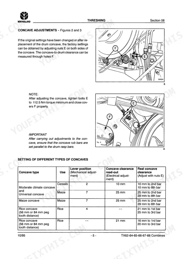
| Threshing | 115-126 | Threshing Cylinder and Concave, Concave Clearance and Cylinder Speed, Threshing Drive |
| Separation | 127-148 | Straw Walkers and Separation Grate, Separation Drive and Bearings |
| Cleaning | 149-180 | Cleaning Shoe, Sieves and Chaffer, Cleaning Fan and Drive, Returns System, Shoe Levelling |
| Grain Storage | 181-202 | Grain Tank and Level Sensors, Unloading Tube and Auger, Unloading Drive and Control |
| Straw Chopper | 203-220 | Straw Chopper and Spreader, Spreader Plate Position, Chopper Drive and Safety Switch |
| Engine | 221-230 | Engine Installation and Mountings, Cooling Package, Air Cleaner and Restriction Sender, Engine Ancillaries |
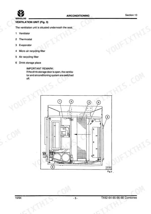
| Airconditioning | 231-242 | Cab Heating, Ventilation and Air Conditioning, Compressor and Condenser, Refrigerant Handling |
| Hydraulic System | 243-308 | Hydraulic Pump and Supply Circuit, Control Valves, Header Lift and Reel Circuits, Unloading Tube Circuit, Pressure Testing |
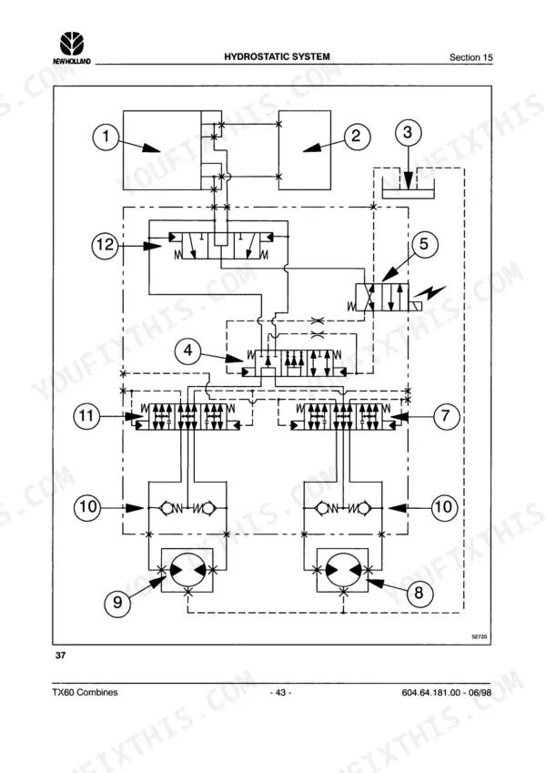
| Hydrostatic System | 309-394 | Hydrostatic Pump and Drive Motor, Charge Circuit, Ground Drive Control, Hydrostatic Pressure Testing and Overhaul |
| Electrical System: General Information and Component Location | 395-440 | How to Read the Diagrams, Explanation of Symbols, And the Location of the Main Electrical Components on the Machine |
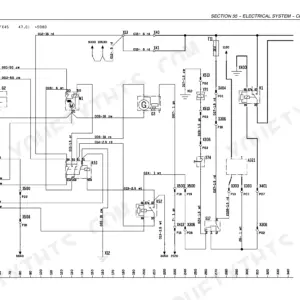
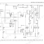
| Electrical System: Circuit Diagrams | 441-924 | Complete Circuit Diagrams by Function and by Model, With Component Keys Naming Every Relay, Fuse, Sender, Gauge and Solenoid and the Diagram Line It Appears on |
| Electrical System: Troubleshooting | 925-1030 | Flow-Chart Troubleshooting per Circuit, For Example Header Lift Control with the Exact Voltages to Expect at Each Control-Module Pin |
| Electrical System: Calibrations | 1031-1050 | InfoView Monitor Calibration, Header Calibration and Ground Speed Calibration |
Quick Reference Specifications
| Specification | Value | Page |
|---|---|---|
| TX60 series | ||
| Models covered | TX62, TX63, TX64, TX65, TX66, TX67, TX68 | |
| Header height control module A3 | ||
| Voltage at X57/08, header oil pressure sensor B13 at maximum pressure | 7.5 volts, which is 75 percent of the voltage at X57/39 | |
| Voltage at X57/08, sensor B13 at minimum pressure | 2.0 volts, which is 20 percent of the voltage at X57/39 | |
| Stabilised input voltage at X57/06 | 70 percent of the output voltage at X57/39 with the lift cylinders 1 cm from end of stroke | |
| Calibrations | ||
| Procedures included | InfoView monitor, header, ground speed | |
| This PDF | ||
| Searchable text | No (page scan) | |
New Holland TX60 Series (TX62-TX68) Common Problems This Manual Covers
The header drops suddenly during operation, or will not reach minimum or maximum height.
The troubleshooting chart handles both, and it starts with a measurement rather than a part. Disconnect the header height sensor R4, lift the header to end of stroke, then check the voltage at X57/08 of the header height control module A3: it should read 7.5 volts with pressure sensor B13 at maximum pressure and 2.0 volts at minimum. If those are wrong, the chart sends you to specific wires, 238 Br and 237 Gn, before it ever suggests replacing the module.
Manual Section: Section 16 - Electrical System: TroubleshootingA gauge, warning lamp or buzzer behaves oddly and you cannot find its circuit.
Use the component key that accompanies each circuit diagram. Every relay, fuse, sender, gauge and solenoid is listed with its designation and the diagram line it appears on, so B4 hydrostatic oil pressure or H9 unloading tube open can be found in seconds. The diagrams are also grouped by model and serial-number range, so check you are reading the sheet that matches your machine.
Manual Section: Section 16 - Electrical System: Circuit DiagramsHeader height or ground speed readings are wrong after a repair.
Recalibrate rather than adjust. The electrical section closes with three calibration procedures: the InfoView monitor, the header and the ground speed. A sensor that has been disturbed or replaced will read plausibly but wrongly until it is calibrated, and the troubleshooting charts assume calibration has already been done.
Manual Section: Section 16 - Electrical System: CalibrationsFrequently Asked Questions
Which combines does this manual cover?
The TX60 series as a family: TX62, TX63, TX64, TX65, TX66, TX67 and TX68. The circuit diagrams name the models and their serial-number ranges on each sheet, so you can see at a glance whether a given diagram applies to your machine.
Can I search the text in this PDF?
No. This document is a page scan without a text layer, so text search and copy will not work. It prints cleanly and every page is legible, and the bookmarks let you jump straight to a section, but plan to navigate by the contents and the section numbers rather than by searching.
How useful is the electrical section?
It is the reason to have the book. It gives the diagram conventions and symbol key, the location of every main component on the machine, the circuit diagrams with a full component key naming each relay, fuse, sender, gauge and solenoid against its diagram line, flow-chart troubleshooting per circuit, and the calibration procedures.
What kind of detail do the troubleshooting charts give?
Real measurements at real pins. For a header that drops suddenly, the chart has you disconnect the header height sensor R4 and check the voltage at X57/08 of the header height control module A3: 7.5 volts with the oil pressure sensor B13 at maximum pressure and 2.0 volts at minimum, which are 75 and 20 percent of the voltage at X57/39. It then branches to the exact wire numbers to test.
Which calibrations are covered?
Three, at the end of the electrical section: the InfoView monitor calibration, the header calibration and the ground speed calibration.
What format is this New Holland TX62–TX68 Series manual in?
You get a 1050-page searchable PDF (34 MB) that downloads instantly after checkout. Open it on your laptop, tablet, or phone, and bring it right to the shop floor.
Is this New Holland TX62–TX68 Series Service Manual printable?
Absolutely. No DRM or copy protection. Print the whole manual or just the pages you need. Any home or office printer works.






Reviews
There are no reviews yet.