

Part of the New Holland Repair Manuals.
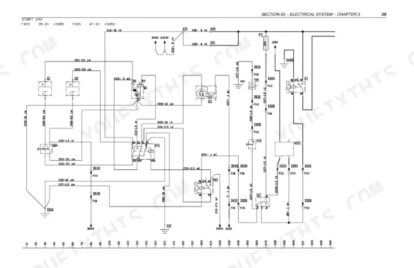
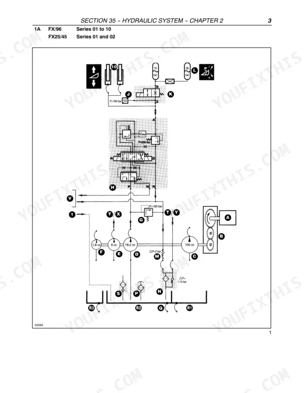
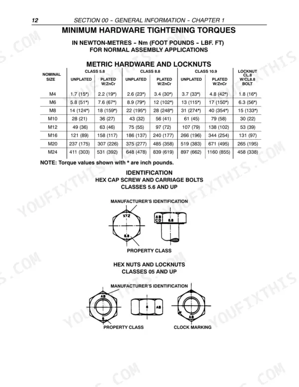
All 890 pages of this New Holland FX25–FX58 series repair manual PDF (OEM #87051240) exist for one reason: putting your FX25, FX28, FX38, FX45, FX48, or FX58 forage harvester back in the field. You get wiring diagrams for the starter, hydrostatic control, and CPU circuits, hydraulic schematics tracing the work, steering, and Hi-Flow systems, and a heavy troubleshooting section that decodes machine and Caterpillar error messages plus CAN identifiers. Step-by-step procedures walk you through splitting the main drive gearbox, pulling the cutterhead, and rebuilding the blower gearbox. Torque the cylinder head bolts to 150 Nm and hold knife-to-side-plate clearance under 3.2 mm; the factory numbers are all here. No more chasing electrical gremlins with a multimeter and a prayer. Bookmarked chapters and a full text layer let you jump straight to any spec right from your phone in the shop.
What's Inside This New Holland FX25–FX58 Series Repair Manual
| System | Pages | Key Topics |
|---|---|---|
| General Information | 1-32 | General Instructions, Safety Regulations |
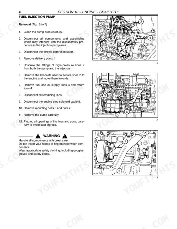
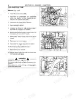
| Engine | 33-40 | Cylinder Head Bolts, Valve Clearance, Fuel Injectors, Removal and Installation of Fuel Injection Pump, Timing, Cooling System |
| Live P.T.O | 41-78 | Removal of the Main Drive Gearbox (Removal of Shields and Doors, Removal of P.T.O. Shafts, Removal of the Battery Box, Removal of the Fuel Reservoir, Removal of the Main Drive Belt Assembly, Removal of the Hydraulic and the Hydrostatic Pump Assembly, Replacing the Rubber Damper on the Engine Output Shaft, Splitting the Main Drive Gearbox, Disassembly and Assembly of the Components in the Rear Half of the Gearbox, Disassembly and Assembly of the Front Half of the Gearbox, Removal and Disassembly of Hydraulic Clutch, Removal and Installation of the Pressure Hose, Replacing Clutch Plates, Replacing the Seals in the Clutch, Removal and Installation of the Clutch Driven Shaft, Installation of the Clutch Into the Gearbox Half, Connecting the Two Gearbox Halves Together, Installation of the Main Drive Gearbox, Installing the Main Drive Gearbox, Installation of the Hydraulic and the Hydrostatic Pump Assemblies, Installation of the Main Drive Belt Assembly, Installation of the Fuel Reservoir, Installing the Battery Box and the Batteries, Installing the PTO Shafts, Starting Up the Forage Harvester) |
| Transmission | 79-92 | Lubrication, Gearbox Shafts and Shifting Diagram, Disassembly of Traction Gearbox, Assembly of Traction Gearbox |
| Wd Lines | 93-98 | Removal From the Base Unit, Disassembly of 4WD Angle Gearbox, Assembly of 4WD Angle Gearbox, Installation on Base Unit |
| Front Mechanical Drive | 99-104 | Lubrication, Disassembly and Assembly of Final Drives |
| Hydrostatic Transmission | 105-120 | Lubrication, Hydrostatic Circuit and Components, Filling and Bleeding the Hydrostatic System, Hydrostatic Pump - Characteristics, Operation of the Multifunction Valve |
| Brakes and Control | 121-128 | Parking Brake Adjustment, Brake Linings, Brake Cylinders, Bleeding the Brakes, Disassembly and Assembly of Brake Shoes and Discs |
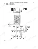
| Hydraulic System | 129-236 | General, Work Hydraulics Attachment Height Control, Work Hydraulics Base Unit, Steering Hydraulics, Low Pressure Hydraulics, Hi-Flow Hydraulics |
| Cab Climate Control | 237-246 | Correct Use of the Air Conditioning System, Storage Maintenance, Air Conditioning Circuit and Component Specifications, Compressor Clutch Replacement, Ventilation Unit |
| Electrical Circuits | 247-266 | Wiring Diagram Standards, Color Codes, Wire Identification, Fuses, Symbols, Connectors |
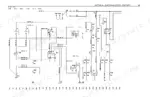
| Wiring Diagrams Fx Na | 267-524 | Starter Circuit, Engine Throttle Control, Hydrostatic Control, Four-Wheel Drive, Electronic System, Instrument Panel, Cpu Inputs and Display |
| CAN Network Basics | 525-542 | CAN Network Layout, Electronic Components, CAN Spy Mode, Decimal and Hexadecimal Counting, Fault Finding Routine |
| Calibration | 543-568 | Machine Calibration with Laptop, Pdt Tool Operation, Serial Number Input, Hydrostatic Pump Calibration, Air Conditioning Calibration |
| Software Update | 569-576 | Software Update with Laptop, Software Update with Pdt Tool, Installation Guide |
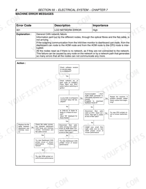
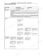
| Troubleshooting | 577-762 | Error Messages Overview, Machine Error Messages, Caterpillar Error Messages, List of CAN Identifiers, Detailed Analysis per Function |
| Product Feed | 763-840 | Removal and Installation of Lower Feed Rolls, Inspection Between Upper Feed Rolls and Cutterhead, Flip Down Upper Feed Rolls |
| Cutterhead | 841-878 | Splitting of Components, Attaching and Detaching the Attachment, Removal - Installation of Chopper Body with A-Frame, Removal - Installation of Chopper Body with Hydraulic Jack |
| Ejection | 879-890 | Inspection Between Cutterhead and Blower, Removal and Installation of Blower, Removal and Installation of Blower Gearbox, Disassembly and Assembly of Blower Gearbox |
Quick Reference Specifications
| Specification | Value | Page |
|---|---|---|
| Sharpening stone electric motor coil resistance | 0.4-1 ohm | p. 627 |
| Bearing housing bolts torque | 240 Nm | p. 865 |
| Maximum allowed distance between the outer end of a knife and the chopper body side plate | 3.2 mm | p. 864 |
| Mounting bolts 2 torque | 180 Nm | p. 876 |
| Cylinder head bolt tightening torque | 150 Nm | p. 34 |
| Injector mounting bolts torque | 21 Nm | p. 35 |
| Rubber damper fastening screws torque | 400 Nm | p. 53 |
| Traction gearbox oil capacity | 15 litres | p. 80 |
| Final drive gearbox oil capacity | 5 litres | p. 100 |
| Hydrostatic transmission reservoir capacity | 38 litres | p. 107 |
| Hydrostatic transmission system capacity | 93 litres | p. 107 |
New Holland FX25–FX58 Series Common Problems This Manual Covers
New Holland FX58 automatic grease system failure lamp flashing at startup, warning stays on during operation
Check supply voltage on pin 3 and the earth connection if no code appears at ignition. A 0.5 second on, 0.5 second off flash means minimum grease level; refill the reservoir. A lamp burning 2 minutes after a cycle, per the error chart, means an empty reservoir, main line leak, trapped air, damaged O-ring, or failed shuttle valve.
Manual Section: Electrical System - TroubleshootingAdjustomatic knife sharpening won't start, sharpening warning light on, cutterhead knives stay dull
Verify cutterhead speed is above the minimum threshold before blaming the sharpening system. Test the sharpening stone drive motor: coil resistance should measure 0.4 to 1 ohm, per the procedure on page 627. Replace a worn stone, inspect the knives for wear, and confirm the shear bar has not reached the end of its travel.
Manual Section: Electrical System - Troubleshooting p. 627Chop length uneven and cutterhead vibrating after knife replacement, ragged cut in heavy crop
Measure the gap between the outer end of each knife and the chopper body side plate; anything over 3.2 mm, the limit shown on page 864, means a mispositioned or wrong-length knife. Reposition or replace knives in matched pairs, then torque the cutterhead bearing housing bolts to 240 Nm if they were disturbed.
Manual Section: Cutterhead - Chopping p. 864Hydrostatic drive jerky or no ground speed after transmission pump service, machine creeps in neutral
Fill and bleed the hydrostatic system completely after any pump or line work; trapped air causes jerky response. Fill the reservoir to its 38 litre capacity and keep extra oil on hand, since the full system holds 93 litres, both listed on page 107. Recheck the level after the first few minutes of operation.
Manual Section: Hydrostatic Transmission p. 107Engine runs rough under load with white exhaust smoke, hard starting when cold
Test the fuel injectors before tearing into the engine; a leaking or stuck injector causes rough running and white smoke. Torque the injector mounting bolts to 21 Nm on reinstallation, per the spec on page 35. While in there, check valve clearance and confirm injection pump timing using the procedures starting on page 36.
Manual Section: Engine - Iveco Aifo Engine p. 35Frequently Asked Questions
How do you calibrate the ground speed on a New Holland FX series forage harvester?
To calibrate the ground speed, use a laptop with the machine calibration program or the PDT tool. Connect the update cable to the instrument panel, type 'CANMENU', then 'FX', and finally 'CALIBR' to start the procedure. Follow the on-screen instructions for 'Minimum forward current to hydrostatic pump' and 'Minimum backward current to hydrostatic pump' by driving the machine in second or third gear at low idle until it starts to crawl. p. 545
What are the replacement specifications for the engine oil and filter service interval?
For the engine, check the oil level daily. Change the oil and filters after the first 100 operating hours. For FX28-38-48 models, change every 300 hours, and for FX58 models, change every 250 hours. p. 31
What is the torque specification for the cylinder head bolts?
The cylinder head bolts must be tightened to 150 Nm. After the initial tightening, repeat the sequence at the same torque, then tighten the bolts in the same sequence over 2 x 120° in 2 steps. p. 34
What is the oil capacity and specification for the traction gearbox?
The traction gearbox has a capacity of 15 litres. Use AMBRA HYPOIDE 90 oil (ref. NH520A) or an oil meeting API GL5 or MIL-L-2105 D specifications with a viscosity grade of SAE 80W-90. p. 80
What is the procedure for adjusting the parking brake?
Disengage the handbrake in the cab and ensure the dimension is 219 mm. Loosen lock nuts C and bolts D. Adjust the dimension to 219 mm using nuts E, then tighten bolts D by hand until they touch the brake blocks. The adjustment is correct when the tension begins at the 6th or 7th tooth of the locking ratchet. p. 122
How is this New Holland FX25–FX58 Series Repair Manual delivered?
Delivery is instant: a 890-page searchable PDF is yours the second checkout clears. Laptop, tablet, or phone, all fine.
Is this New Holland FX25–FX58 Series manual print-friendly?
Yes. No DRM, nothing blocks printing, so run off the pages you need on whatever printer you have.






Reviews
There are no reviews yet.