Part of the New Holland Repair Manuals.
A tech with a pressure gauge teed into the pump port and an E215C idling at full throttle needs one number: what the main relief should read. That figure, and the test procedure that puts the machine in the right state to read it, are both in this 860 page New Holland service manual covering the E215C and E245C crawler excavators, publication 84550265A.
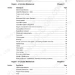
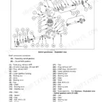
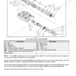
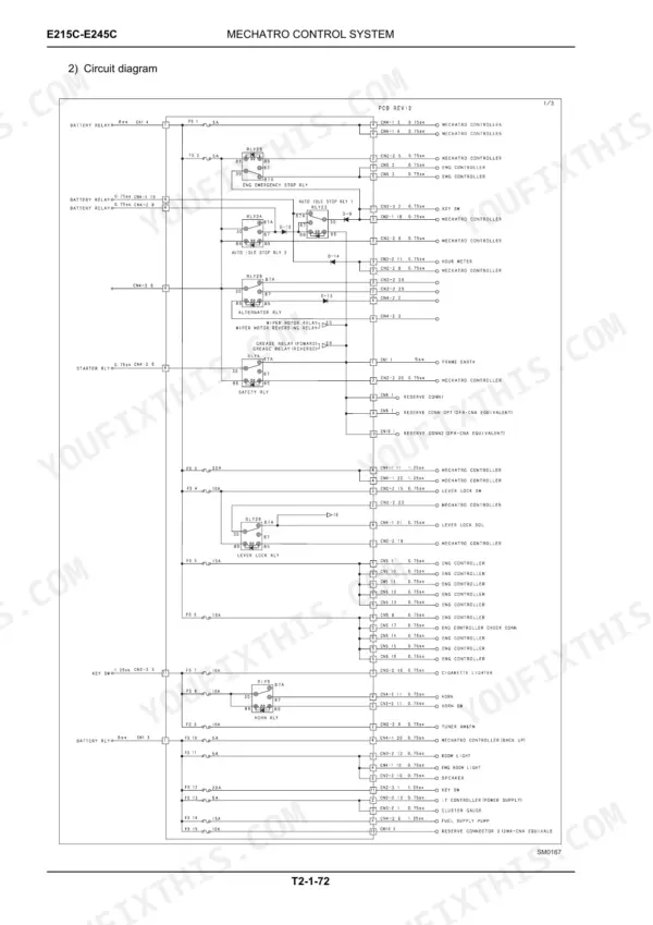
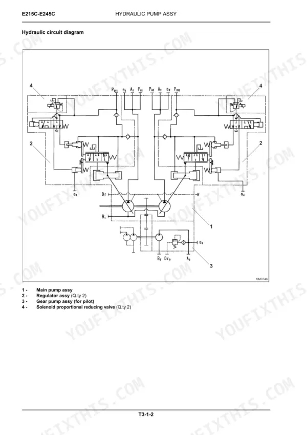
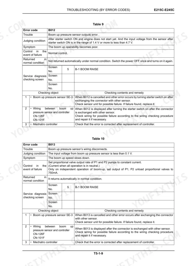
Coverage runs from the Mechatro control system, hydraulic and electrical systems through component operation of the pump device, control valve, swing device, travel device and cylinders, then into standard performance tests, error code troubleshooting, and repair instructions for the upperstructure, undercarriage and front attachment. The F4HFE613S*A002 engine has its own troubleshooting coverage.
It arrives as a PDF download. Print the track adjuster or final drive pages, carry them to the bench, and let them get dirty.
What's Inside This New Holland E215C, E245C Manual
| System | Pages | Key Topics |
|---|---|---|
| General Safety Information | 5-17 | Safety Rules, Starting, Operating, Stopping, Maintenance, Transfers and Transportation |
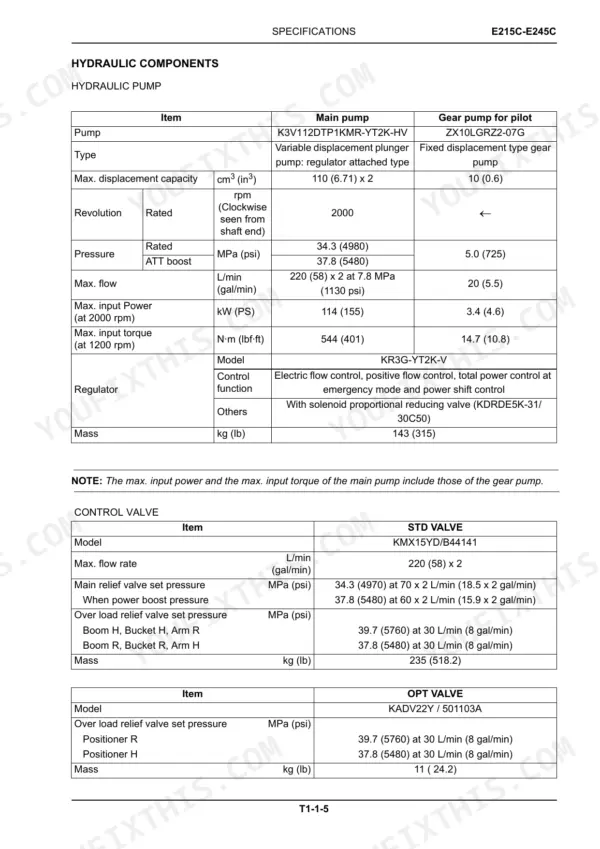
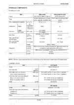
| Operational Principle - General Information | 59-82 | Machine Main Components, Hydraulic Components, Engine Specifications, Dimensions and Weights, Fluids and Lubricants |
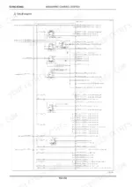
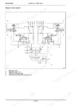
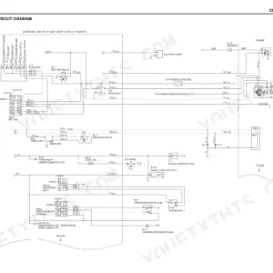
| Operational Principle - System | 83-174 | System (Mechatro Control System, Hydraulic System, Electrical System), Travel Straight Control, Self Diagnosis Display, Travel Circuit, Electrical System Diagram, Wiring Harness |
| Operational Principle - Component Operation | 177-350 | Pilot Valve, Control Valve, Swing Device, Travel Device, Swivel Joint |
| Operational Performance Test | 353-386 | Introduction, Standard Performances, Test Procedures, Mechatro Controller |
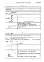
| Troubleshooting | 389-506 | Troubleshooting by Error Codes, Hydraulic System Troubleshooting, Electric Systems Troubleshooting, Engine Troubleshooting |
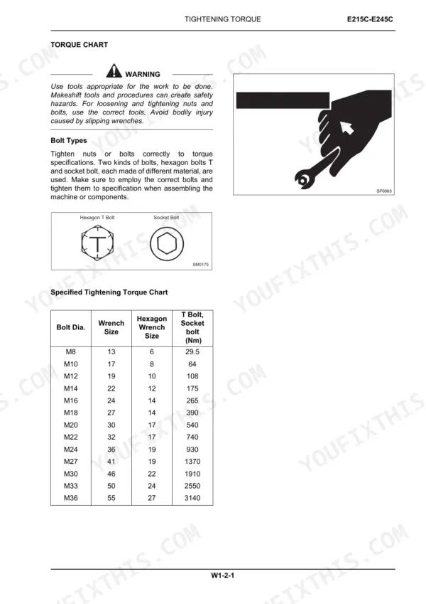
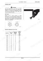
| Repair Instructions - General Information | 509-524 | Precautions for Disassembly, Torque Chart, Piping Joint |
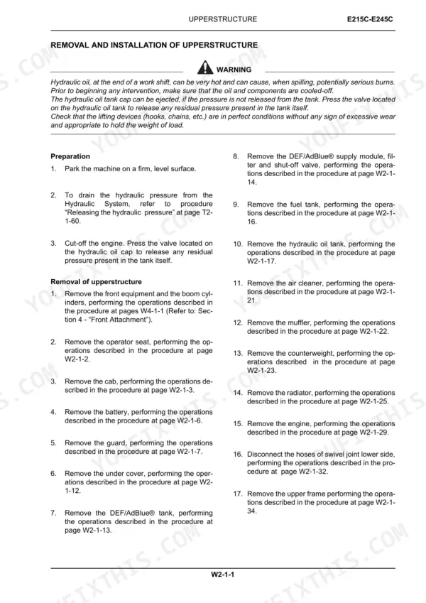
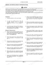
| Repair Instructions - Upperstructure | 525-624 | Upperstructure (Pump Device, Control Valve, Swing Device, Pilot Valve), Removal and Installation of the Cab, Fuel Tank, Radiator, Upper Frame |
| Repair Instructions - Undercarriage | 665-818 | Swing Bearing, Track Adjuster, Front Idler, Upper and Lower Roller, Tracks |
| Repair Instructions - Front Attachment | 819-860 | Replacement of Bucket, Cylinders Removal and Installation, Cylinders Assembly and Disassembly |
Quick Reference Specifications
| Specification | Value | Page |
|---|---|---|
| E215C | ||
| Travel device reduction gear unit tightening torque | 279 ± 29 Nm (206 ± 21 lbf·ft) | p. 669 |
| Sprocket standard diameter (A) | 84 (3.307) mm (in) | p. 788 |
| Sprocket standard width (B) | 160 (6.299) mm (in) | p. 788 |
| Hydraulic Oil Tank Capacity | 172 L | p. 80 |
| E245C | ||
| Upper roller capscrew (2) M16x120 tightening torque | 279 ± 29 Nm (206 ± 21.4 lbf·ft) | p. 790 |
| Hydraulic Oil Tank Capacity | 167 L | p. 81 |
| All Models | ||
| Engine Oil Capacity | 17 L | p. 80 |
| Main Relief Valve Pressure (Standard) | 34.3 MPa | p. 65 |
| Engine Rated Output Power | 129 kW | p. 68 |
| Engine Maximum Torque | 740 Nm | p. 68 |
| Travel Motor Relief Valve Pressure (Cracking) | 311 bar | p. 67 |
| Travel Motor Relief Valve Pressure (Total Flow) | 353 bar | p. 67 |