
This 272-page Perkins 4006-23TAG1A, TAG2A, and TAG3A workshop manual PDF (OEM #TPD 1511E) walks your inline diesel engine from cylinder head teardown to flywheel housing reassembly using genuine Perkins factory procedures. You get wiring diagrams for the alternator, starter motor, and digital electronic governor, plus factory error codes and a troubleshooting section for tracing faults fast. Inside: engine timing procedures (setting number 1 piston to TDC, calibrating fuel injectors, zeroing the governor), exploded views of every major assembly, and a full special tools section covering the liner extractor and injector clamp. Torque the fuel injector nozzle nuts to 205 Nm (150 lbf ft) and the governor adjustable link to 8 Nm. Quit guessing which wire feeds the stop solenoid. Bookmarked for quick jumps; download it, pull it up on your phone next to the engine, and get wrenching.
What's Inside This Perkins 4006-23 TAG Series Manual
| System | Pages | Key Topics |
|---|---|---|
| General Information | 13-20 | Introduction, Engine Views, Engine Identification, Viton Seals, Engine Lift Equipment, Powerpart Recommended Consumable Products |
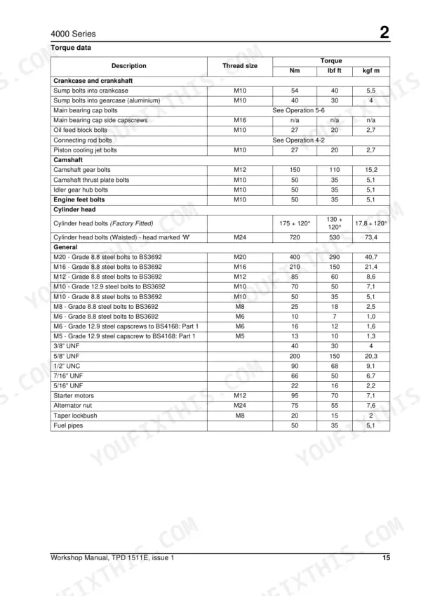
| Specifications | 21-28 | Basic Engine Data, Data and Dimensions, Rocker Assembly, Valves, Piston and Connecting Rod, Torque Data |
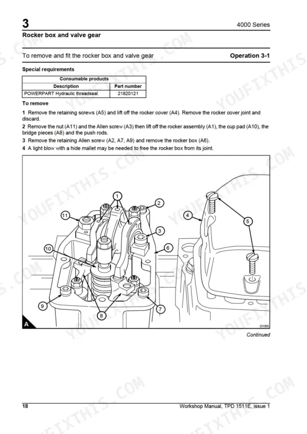
| Cylinder Head Assembly | 29-50 | General Description, Rocker Box and Valve Gear, Valve Gear, Cylinder Head Operations, Valves and Components, Fuel Injector Bush, Manifolds |
| Piston and Connecting Rod Assemblies | 51-66 | General Description, Piston and Connecting Rod Removal, Piston Rings, Piston and Connecting Rod Assembly, Piston and Connecting Rod Inspection, Small End Bush, Piston Cooling Jets |
| Crankshaft Assembly | 67-76 | General Description, Crankshaft Pulley and Adaptor, Crankshaft Vibration Damper Assembly, Crankshaft |
| Gearcase and Drive Assembly | 77-96 | General Description, Gearcase, Front Oil Seal, Camshaft Gear, Idler Gear, Cam Followers, Camshaft, Crankshaft Gear |
| Crankcase | 97-102 | General Description, Crankcase Operations, Cylinder Liner |
| Engine Timing | 103-110 | Set Number 1 Piston to TDC, Calibrating Fuel Injectors, Setting Governor on Zero Fuel, Applying Pressure to Timing Pin, Timing Fuel Injectors |
| Aspiration System | 111-126 | General Description, Air Filter System, Turbocharger, Air Pipe Connection, Engine Breather |
| Lubrication System | 127-146 | General Description, Oil Filters, Oil Sump and Dipstick, Oil Strainer and Suction Pipe, Lubricating Oil Pump, Relief Valve, Fuel Lift Pump Drive Unit |
| Fuel System | 147-169 | General Description, Fuel Filter, Fuel Injector Unit, Test and Set Fuel Injector, Fuel Lift Pump, Fuel Control Shaft |
| Cooling System | 170-194 | Coolant Pipework, Thermostat, Thermostat Housing, Coolant Pump, Fan System, Lubricating Oil Cooler, Radiator |
| Flywheel and Housing | 195-202 | General Description, Flywheel, Gear Ring, Flywheel Housing, Flywheel Housing Oil Seal |
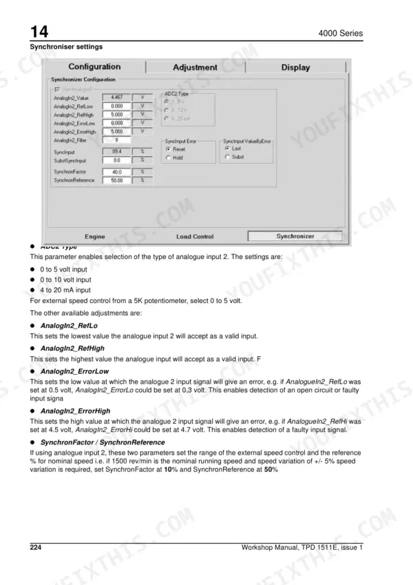
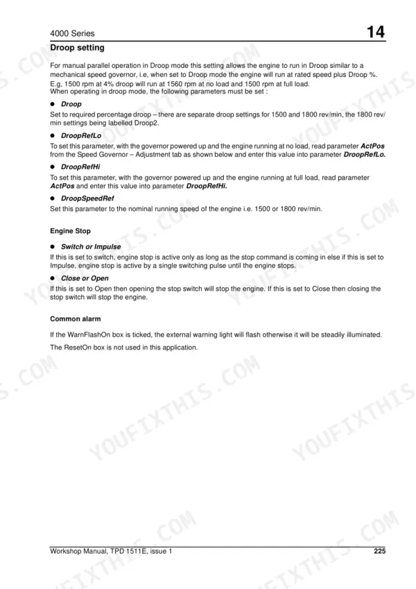
| Electrical Equipment | 203-257 | General Description, Alternator, Starter Motor, Air Starter Motor System, Stop Solenoid, Digital Electronic Governor Overview, Governor Adjustments and Settings |
| Auxiliary Equipment | 258-263 | Ren Valve, Immersion Heater |
| Special Tools | 264-272 | Piston Slip Ring, Gearcase Oil Seal Fitting Tool, Camshaft Guide Tube, Fuel Injector Clamp and Fuel Feed Adaptor, Liner Extractor, Flywheel Housing Oil Seal Fitting Tool |
Quick Reference Specifications
| Specification | Value | Page |
|---|---|---|
| Fuel injector bush | Operation 3-9 To remove and fit a fuel injector bush | p. 4 |
| Nuts, fuel injector nozzle to nozzle holder | 205 Nm (150 lbf ft) 5,9 kgf m | p. 28 |
| adjustable link torque | 8 Nm (6 lbf ft) 0.6 kgf m | p. 90 |
| Air filter bracket, bolts (A2) torque | 50 Nm (36.8 lbf ft) 5 kgf m | p. 132 |
| Air filter bracket, bolts (B1) and nuts (B7) torque | 50 Nm (36.8 lbf ft) 5 kgf m | p. 132 |
| Oil filter capacity | approximately 5 litres (1 gal) | p. 129 |
| Filter head setscrews torque | 50 Nm (36.88 lbf ft) 5,09 kgf m | p. 130 |
| Fuel injector unit puller | T6253/350 | p. 149 |
| retainer nut torque | 25 Nm (18,4 lbf ft) | p. 179 |
| Torque for nut on drive shaft of coolant pump | 230 Nm (170 lbf ft) 23,4 kgf m | p. 178 |
| Torque for setscrews, bolt and nut for coolant pump | 50 Nm (36.9 lbf ft) 5,1 kgf m | p. 28 |
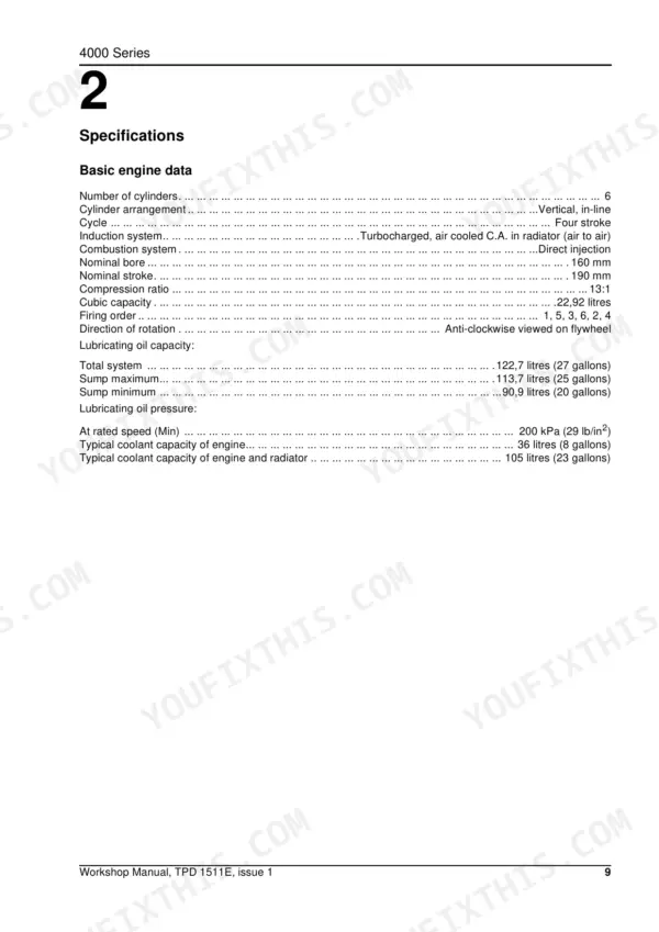
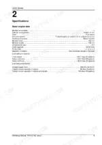
| Number of cylinders | 6 | p. 21 |
Perkins 4006-23 TAG Series Common Problems This Manual Covers
Perkins 4006-23 injector nozzles dribbling, white smoke and rough running at low load
Pull the injector units with puller T6253/350 and bench test the opening pressure. Adjust shim thickness to correct it; adding 0.0508 mm (0.002 in) of shim raises pressure roughly 517 kPa (75 lbf/in²). Tighten the nozzle nut to 205 Nm (151 lbf ft) with a long 27 mm socket, page 141 covers the full procedure.
Manual Section: Fuel System p. 141Engine RPM hunts and surges under load, governor linkage feels loose at the control shaft
Check stored governor error codes against the reference, then work through the troubleshooting procedures. Inspect the linkage for worn ball joints and slop. Retorque the adjustable link to 8 Nm (6 lbf ft) and the control shaft front support bearing setscrews to 8 Nm (6 lb ft) before retesting under load.
Manual Section: Electrical EquipmentLow oil pressure alarm E01 trips at rated speed right after an oil and filter change
Verify sump level first; the sump holds approximately 114 litres (25 gals) and each oil filter takes another 5 litres (1 gal), so a filter change without topping up drops the level fast. Confirm pressure holds at least 200 kPa at rated speed. Torque filter head setscrews to 50 Nm (36.88 lbf ft) if the housing weeps.
Manual Section: Lubrication System p. 131Coolant temperature climbs under full load, high water temperature alarm shuts the engine down
Check coolant level and inspect the pump for shaft play or seal weep before condemning the head. If the pump is worn, replace it: torque the drive gear nut to 230 Nm (170 lbf ft) as detailed on page 178, and the mounting setscrews, bolt and nut to 50 Nm (36.9 lbf ft). Flush the system before refilling.
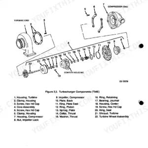
Manual Section: Cooling System p. 178Turbocharger whines, blue smoke from exhaust, boost pressure drops off after 3000 hours
Inspect the turbocharger for shaft play and oil pooling in the compressor housing, then trace the oil feed line for restriction or coking. Verify lubricating oil pressure holds at least 200 kPa at rated speed; a starved turbo fails fast. Follow the removal and inspection steps in the Aspiration System section starting on page 111.
Manual Section: Aspiration System p. 111Frequently Asked Questions
How to reset Perkins 4006-23TAG3A engine fault codes after servicing?
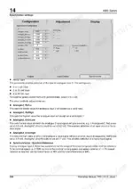
To clear current error codes after servicing, open the “Error – Current Errors” menu in the Pandaros Package software. Once the current errors have been physically resolved, use the “clear errors button” on the screen. To clean the time stamp screen, click the “reset time stamp button”. p. 252
What are the torque specs for Perkins 4006-23TAG1A/2A/3A cylinder head bolts?
For factory-fitted cylinder head bolts, the torque is 175 Nm plus an additional 120° turn. For waisted cylinder head bolts marked 'W' (M24), the torque is 720 Nm (530 lbf ft, 73,4 kgf m). The fitting procedure involves five stages, with the final stage tightening to 715 Nm (530 lbf ft) 73,9 kgf m. p. 27
Torque specification for Perkins 4006-23TAG3A turbocharger mounting bolts
The bolts securing the turbocharger to the adaptor should be tightened to 50 Nm (36.8 lbf ft) 5 kgf m. The V-band clamp for the exhaust elbow should be tightened to 9.5 Nm (7 lbf ft) 0.9 kgf m. p. 107
What is the total lubricating oil capacity for the Perkins 4000 Series engine?
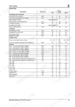
The total lubricating oil capacity for the system is 122.7 litres (27 gallons). The sump maximum capacity is 113.7 litres (25 gallons), and the sump minimum capacity is 90.9 litres (20 gallons). p. 21
What is the typical coolant capacity for the Perkins 4000 Series engine and radiator?
The typical coolant capacity for the engine alone is 36 litres (8 gallons). When including the radiator, the typical coolant capacity for the engine and radiator system is 105 litres (23 gallons). p. 21
How quickly can I access this Perkins 4006-23 TAG1A manual after buying?
This is a 272-page searchable PDF ready for immediate download. Works on any device, so pull it up on your phone while you're under the hood. No shipping, no waiting.
Is this Perkins 4006-23 TAG1A Workshop Manual printable?
No restrictions at all. Print individual pages, full chapters, or the entire manual. The PDF is completely unlocked.
Reviews
There are no reviews yet.