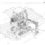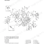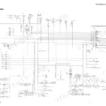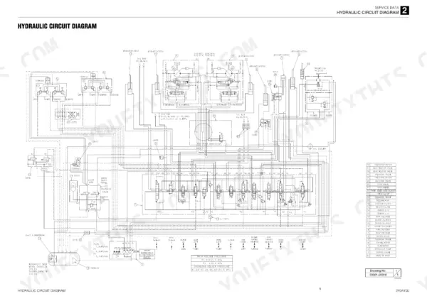
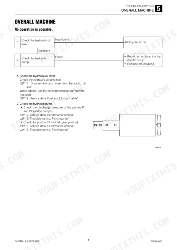
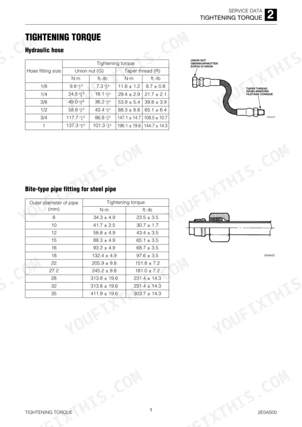
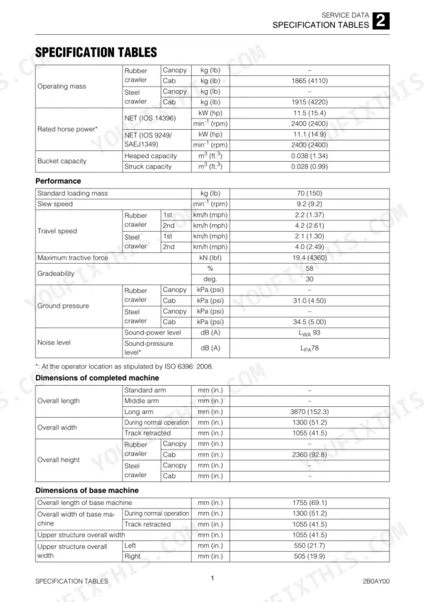
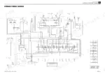
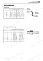
Takeuchi's own service data for the TB216 mini excavator is settled in one 301-page book, OEM ID CC6E001, supplied as this Takeuchi TB216 service manual PDF. Hydraulic and electrical circuit diagrams sit with the specification tables, lubricant and fuel chart and tightening torques, and a function chapter explains the piston pump, gear pump, control valve and pilot valve. Disassembly and assembly covers travel, slew, upper frame and attachments; troubleshooting is sorted by symptom, from traveling and slewing to boom, arm, bucket and dozer blade. Check pumps P1 and P2 for 16.8 L/min (4.44 US gal./min.) each, and set the boom, arm and dozer blade relief valve lock nut to 30 ± 2 N·m. Refitted a cylinder? Bleed it by extending and retracting 4 or 5 times, stopping your rod 100 mm (3.9 in.) short of stroke end. Bookmarks and a searchable text layer keep that bleed and your relief valve work tied to Takeuchi's figures.
What's Inside This Takeuchi TB216 Manual
| System | Pages | Key Topics |
|---|---|---|
| Safety | 3-12 | Safety Alert Symbol, Safety Precautions, Cautions When Working |
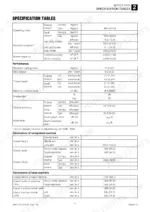
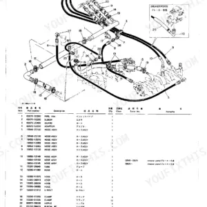
| Service Data | 13-66 | Dimensional Drawing, Specification Tables, Table of Masses, Lubricant and Fuel Chart, Performance Criteria, Tightening Torque, Hydraulic Circuit Diagram, Electrical Circuit Diagram |
| Function | 67-92 | Hydraulic Pump (Piston), Gear Pump, Control Valve, Pilot Valve (Control Lever), Solenoid VALVE (3rd Auxiliary Line Piping) |
| Service Standards | 94-108 | Drive System |
| Travel System | 109-126 | Slew Equipment, Upper Frame |
| Operating Device | 127-142 | Attachments |
| Hydraulic Tank | 143-167 | Hydraulic Pump, Control Valve |
| Pilot Valve | 168-182 | Solenoid Valve (3rd Auxiliary Line Piping), Proportional Control Solenoid Valve, Solenoid Valve (Lever Lock) |
| Cylinders | 183-197 | |
| Travel Motor | 198-213 | |
| Slew Motor | 214-232 | Swivel Joint |
| Troubleshooting | 233-284 | Overall Machine, Traveling, Slewing, Boom, Arm, Bucket, Boom Swing, Dozer Blade |
| Other | 285-301 | Monochrome LCD ClusterPanel Display and LCD Specifications(Without a CAN) |
Quick Reference Specifications
| Specification | Value | Page |
|---|---|---|
| Internal leak limit | 1 mL (0.034 fl.oz) / 3 min or less | p. 197 |
| Lock nut torque for Boom, arm, dozer blade relief valve | 30 ± 2 N·m (22.1 ± 1.5 ft.-lb) | p. 30 |
| Seal tape overlap | 10 mm (0.39 in) | p. 11 |
| Hydraulic pump delivery P1 | 16.8 L/min. (4.44 US gal./min.) | p. 20 |
| Hydraulic pump delivery P2 | 16.8 L/min. (4.44 US gal./min.) | p. 20 |
| Lock nut torque for Pilot pressure relief valve | 15.7 N·m (11.6 ft.-lb) | p. 31 |
| 2nd auxiliary line piping pressure | 20.0 MPa (2900 PSI) | p. 29 |
| 3rd auxiliary line piping (right) pressure | 20.0 MPa (2900 PSI) | p. 29 |
| Main pump displacement P1, P2 | 7.0 cm3/rev (0.4 cu. in./rev) | p. 44 |
| Main pump displacement P3 | 4.5 cm3/rev (0.3 cu. in./rev) | p. 44 |
| Hydraulic hose union nut tightening torque 1/8 | 9.8 +4.9/0 N·m (7.3 +3.5/0 ft.-lb) | p. 38 |
Takeuchi TB216 Common Problems This Manual Covers
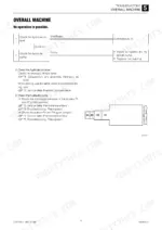
Takeuchi TB216 all hydraulic functions working but insufficient force, with abnormal noise from the piston pump
Check the hydraulic oil level and top up with the same brand already in the tank. A noisy piston pump points to suction line cavitation: grease suspect joints to find air ingress and check the suction filter for clogging. Release hydraulic pressure before opening lines (page 9), then replace seal tape, O-ring and hose. Measure main relief pressure against 21.0 MPa (page 20); no rise after a 1/4 turn of the setscrew means a faulty valve.
Manual Section: Overall machine p. 236Boom, bucket, slew and arm functions all fail to move or operate too slowly
Check pilot supply gear pump P4 against 3.4 MPa (page 20) and clean a clogged line filter. Check the pilot solenoid fuse, then confirm voltage at the lever lock solenoid valve with the lever stand in driving position. Key ON, press the solenoid lightly and cycle the limit switch; no vibration means a bad valve. Measure pilot relief pressure next (page 239).
Manual Section: Overall machine p. 238Right or left travel is impossible, track will not move on one side
Test boom (left travel, R1/P1) and arm (right travel, R2/P2) first; if they are weak, inspect the main relief valve and piston pump. Check spool stroke against 7 mm and look for a loose return spring bolt; replace the housing block if the spool is stuck or scratched (page 241). Release hydraulic pressure per page 9, then remove the counter balance valve plug and push the spool: about 6 mm of smooth travel is normal.
Manual Section: Traveling p. 241Right or left travel speed decelerates and the machine veers to one side
Check crawler belt tension and clear any foreign matter caught in the track, then check spool operation. Release internal hydraulic pressure before disconnecting any hose (page 9). Swap the P1 and P2 discharge hoses: if the veer flips sides, the pumps are faulty, so repair them and replace the oil or filter. Swap the main relief valves between left and right travel circuits; a flipped veer means one relief valve is bad (page 243).
Manual Section: Traveling p. 2432nd-speed travel will not engage when the 2nd speed switch is pressed
Check gear pump 4 and clean a clogged line filter, then test the 2nd speed solenoid fuse. Verify voltage at the switch and harness continuity. Key ON, press the solenoid end lightly and cycle the limit switch; feel for vibration. Release hydraulic pressure first (page 9), then gauge the swivel joint hose at the 2nd speed control valve against 3.4 MPa and inspect that spool for sticking or debris (page 246).
Manual Section: Traveling p. 245Slew motor will not turn the upper frame and no slewing is possible
Test other actuators first; if blade (R3/P3) is weak, check the main relief valve and pump. Release hydraulic pressure per page 9, then gauge the pilot valve to slew block hose: 0 to 3.4 MPa with lever angle is normal (page 248). Check spool supply pressure against 20.0 MPa, then measure slew relief pressure and adjust or replace the relief valve. Repair the slew motor or replace the slew bearing if faulty.
Manual Section: Slewing p. 247Frequently Asked Questions
What are the hydraulic pressure specifications for the Takeuchi TB216?
The main relief valve pressure settings for the TB216 are 21.0 MPa (3050 psi) for the primary circuits, 20.0 MPa (2900 psi) for the dozer blade, and 3.4 MPa (490 psi) for the pilot pressure system. p. 20
Why does my TB216 have insufficient digging force?
Insufficient force can be caused by a low hydraulic oil level, suction line faults (cavitation), a faulty main relief valve, or a faulty piston pump. Check the oil level first, then inspect for abnormal noise from the piston pump indicating cavitation, and test the main relief valve pressure. p. 236
How do I bleed air from the TB216 hydraulic system?
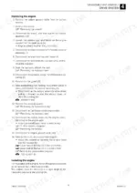
After replacing hydraulic oil, start the engine at idle. Slowly operate each cylinder to release air from the piping. Then, with the engine at slow speed, extend and retract each cylinder 4 or 5 times, moving the piston rod to a position 100 mm (3.9 in.) before the end of the stroke. Finally, run the engine at top speed and move the rod to the stroke end to finish bleeding. p. 146
What is the torque specification for the hydraulic pump mounting bolts on the Takeuchi TB216?
The bolts for the hydraulic pump assembly should be tightened to 102 N·m (75.2 ft.-lb). p. 102
What is the engine coolant capacity for the Takeuchi TB216?
The engine cooling system has a capacity of 3.8 L (4.0 US qt.). p. 25
What do I get after purchasing this Takeuchi TB216 manual?
You get a 301-page searchable PDF that downloads instantly after checkout. Open it on your laptop, tablet, or phone, and bring it right to the shop floor.
Am I free to print this Takeuchi TB216 Service Manual?
Yes. Print a single page or a chapter for your own shop use, on letter or A4.