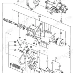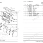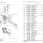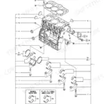


Part of the Yanmar Parts Manuals.
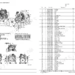
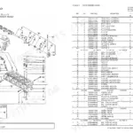
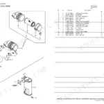
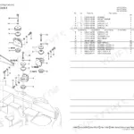
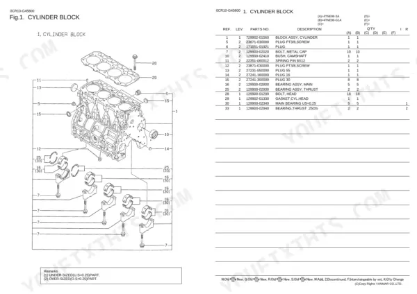
Factory reference OEM #0CR10-G45800 covers both the SA and G1A variants of the 1996 Yanmar 4TNE98 engine. Across 30 pages, this parts catalog details every assembly from the cylinder block to the governor. Each section provides full exploded views with OEM part numbers called out on individual components, including gear housing seals, camshafts, crankshafts, and fuel injection pump internals. Because both configurations are mapped, cross-referencing part numbers between variants is straightforward. Verify the main bearing under-size at 0.25 mm or check the starting motor output (2.3 KW) to ensure accurate sourcing. Stop guessing at suffixes and ordering from memory. The PDF is fully bookmarked by system, allowing fast searches to land on the exact diagram needed.
Other edition of this manual
What's Inside This Parts Manual
| System | Pages | Key Topics |
|---|---|---|
| Cylinder Block | 4 | Cylinder Block Assy, Camshaft Bush, Main Bearing Assy, Thrust Bearing Assy, Cylinder Head Gasket |
| Gear Housing | 5 | Gear Housing Cover, Oil Seal, Fuel Injection Pump Cover, Liquid Gasket, Gear Housing Comp, Lub. Oil Pump Assy, Tachometer Gear Unit, Filler Cover |
| Flywheel Housing & Oil Sump | 6 | Fltwheel Housing, Flywheel Housing, Flywheel Cover Cap, Seal HTC95, Oil Sump Assy, Liquid Gasket |
| Cylinder Head & Bonnet | 7 | Breather Hose, Retainer, Engine Lifter, Cylinder Head Assy, Valve Guide, Suction Valve, Exhaust Valve, Valve Spring |
| Suction Manifold | 8 | Suction Manifold Gasket, Int Manifold, Earth Cord, Gasket, Air Heater |
| Exhaust Manifold | 9 | Gasket, Bolt, Stud |
| Camshaft & Driving Gear | 10 | Tappet, Push Rod, Camshaft Assy, Thrust Metal, Camshaft Gear, Idler Shaft, Idle Gear Assy, Idle Gear Bush |
| Crankshaft & Piston | 11 | Crankshaft Comp, Crankshaft Gear, V-Pulley, Flywheel Assy, Ring Gear, Piston W/ Ring, Ring Set, Connecting Rod Assy |
| Lub.Oil System | 12 | Dipstick, Dipstick Guide, Filter 80X80L, Lub. Oil Pipe Assy, Oil Pressure Switch, Retainer 6X, Round Gasket |
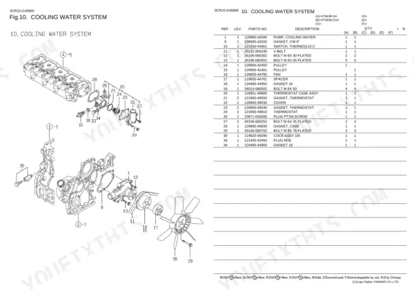
| Cooling Water System | 13 | Cooling Water Pump, Cw-P Gasket, Thermo C Switch, V-Belt, Pulley, Fan, Spacer, Gasket |
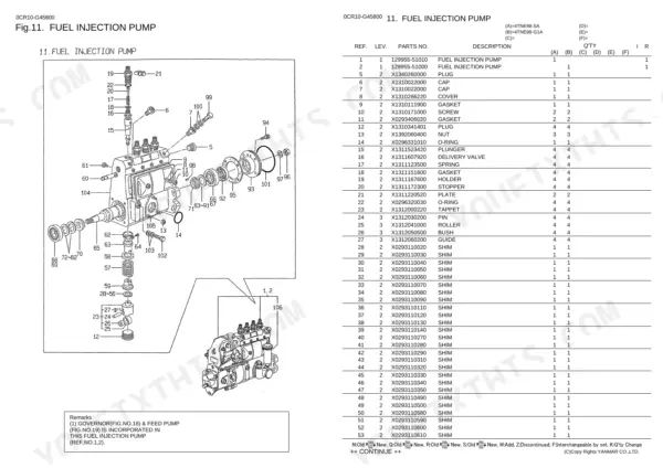
| Fuel Injection Pump | 14-16 | Plunger, Delivery Valve, Tappet, Camshaft, Control Rack |
| Fuel Injection Valve | 17 | Bracket, Fuel Valve, Fuel Injection Valve Assy, Nozzle, Nozzle Holder Assy, Nozzle Spring, Nozzle Spring Seat, Stop Plate |
| Fuel Line | 18 | Fuel Filter, Fuel Filter Body, Round Gasket, Pipe Joint, Fuel Pipe, Joint, Fuel Oil Pipe, Fuel Retn.pipe Joint |
| Engine Stop Device | 19 | Solenoid Bracket, Joint, Solenoid Link, Stop Solenoid |
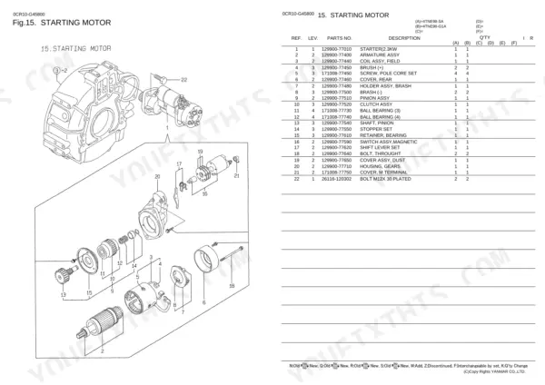
| Starting Motor | 20 | Starter, Armature Assy, Field Coil Assy, Brush, Rear Cover, Brash Holder Assy, Brash, Pinion Assy |
| Generator | 21 | Rotor Assy, Stator Assy, Rear Cover Assy, Regulator Brush Assy, Brush Assy, Fan Side Guide, Diode Assy |
| Gasket Set | 22 | Cylinder Head Gasket, Valve Stem Seal, Nozzle Protector, Nozzle Seat, Bonnet Gasket, Suction Manifold Gasket, Cw-P Gasket |
| Governor | 23-24 | |
| Feed Pump | 25 |
Quick Reference Specifications
| Specification | Value | Page |
|---|---|---|
| Thermostat Opening Temperature | 110 C | p. 13 |
| Starting Motor Power Output | 2.3 KW | p. 20 |
| Main Bearing Under-size | 0.25 mm | p. 4 |