

Part of the Yanmar Repair Manuals.
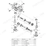
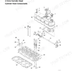
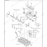
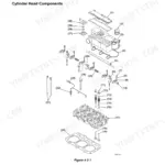
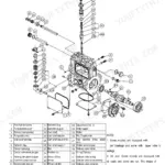
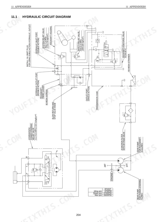
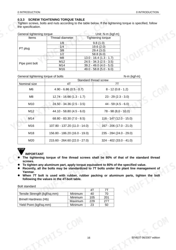
All 218 pages of this Yanmar EF453T Technical Manual are built around one machine: your EF453T diesel tractor, from cold-start fuel circuits to final-drive axle assemblies. Inside, you get complete hydraulic circuit diagrams, a full electrical wiring section covering engine start, charging, alarm, and safety circuits, plus exploded views across every major component group. Torque tables cover every bolt grade: an M10 at 4T grade torques to 24.50–34.36 N-m; step up to 7T hardware and that same M10 calls for 44–59 N-m. Those aren’t forum estimates. Replace your fuel filter every 300 hours or 6 months, whichever comes first; the manual tells you exactly which element goes where. Your machine is down and generic advice costs time you don’t have. Pull up the PDF on any device, search by keyword, jump straight to the section, and get the EF453T running again.
What's Inside This Manual
| System | Pages | Key Topics |
|---|---|---|
| Safety | 3-9 | Symbol Indication, Precautions for the Safe Services, General Precautions for Services, Screw Tightening Torque Table, Safety Label Location, Tractor Mass and Tire Specification |
| Introduction | 10-30 | To the Owner, Important Warranty Information, Declaration of Conformity, Maintenance, Supply Period for Maintenance Parts, Improvements, Symbol Indication |
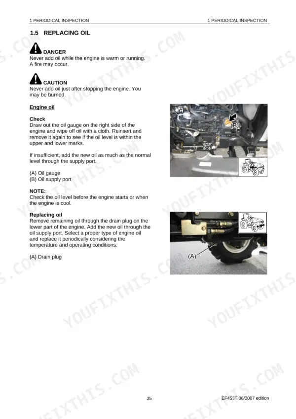
| Periodical Inspection | 31-47 | Check Intervals, Oil and Water Volume, Replacing Oil, Replacing Respective Elements, Replacing Cooling Water, Replacing Radiator Screen and Air Cleaner Elements, Checking Battery |
| Rough Disassembly of Components | 48-70 | Removing the Engine Bonnet Cover, Removing the Fender, Removing the Seat Stay, Clutch Housing, Front Axle Unit |
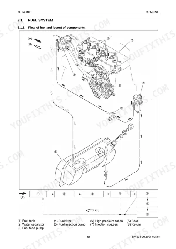
| Engine | 71-107 | Fuel System, Combustion System, Lubricating Oil System, Cooling Water System, Adjustment Specifications, Maintenance Criteria |
| Clutch | 108-112 | Structure and Functions, Disassembly and Assembly |
| Transmission | 113-137 | Power Transmitting Diagram, Transmission System Cross-Section, Transmission System |
| Rear Axle and Brake | 138-146 | Structure and Functions, Disassembly and Assembly |
| Front Axle | 147-155 | Structure and Functions, Cross-Section View, Front Wheel Alignment, Disassembling the Front Bearing Case, Disassembling and Reassembling the Front Differential Section |
| Power Steering | 156-166 | Structure and Functions, Power Steering Valve |
| Hydraulic Lift Unit | 167-188 | Structure and Functions, Assembly and Check, Hydraulic Power Take Off |
| Electric Equipment | 189-212 | Engine Start Circuit, Charging Circuit, Alarm Circuit, Safety Circuit |
| Appendixes | 213-218 | Hydraulic Circuit Diagram, Location of Elect, Electrical Wiring Diagram |
Quick Reference Specifications
| Specification | Value | Page |
|---|---|---|
| General tightening torque for bolts (4T) | M6: 4.90 - 6.86 N-m (0.5 - 0.7 kgf-m), M8: 12.74 - 16.66 N-m (1.3 - 1.7 kgf-m), M10: 24.50 - 34.36 N-m (2.5 - 3.5 kgf-m), M12: 44.10 - 58.80 N-m (4.5 - 6.0 kgf-m), M14: 68.80 - 83.30 N-m (7.0 - 8.5 kgf-m), M16: 107.80 - 137.20 N-m (11.0 - 14.0 kgf-m), M18: 156.80 - 186.20 N-m (16.0 - 19.0 kgf-m), M20: 215.60 - 264.60 N-m (22.0 - 27.0 kgf-m) | p. 25 |
| General tightening torque for bolts (7T) | M6: 8 - 12 N-m (0.8 - 1.2 kgf-m), M8: 23 - 29 N-m (2.3 - 3.0 kgf-m), M10: 44 - 59 N-m (4.5 - 6.0 kgf-m), M12: 78 - 98 N-m (8.0 - 10.0 kgf-m), M14: 118 - 147 N-m (12.0 - 15.0 kgf-m), M16: 167 - 206 N-m (17.0 - 21.0 kgf-m), M18: 235 - 284 N-m (24.0 - 29.0 kgf-m), M20: 324 - 402 N-m (33.0 - 41.0 kgf-m) | p. 25 |
| Battery specification | 12V-64AH | p. 30 |
| Battery part number | 95D31R 1A7780-51500 | p. 192 |
| Fuel filter replacement interval | Every 300 operating hours or 6 months, whichever is earlier | p. 73 |
| Air cleaner element replacement interval (dusty environment) | Every 300 hours | p. 39 |
| Air cleaner element replacement interval (normal condition) | Every 1000 hours | p. 39 |
| Starter motor specification | 12V-1.2KW | p. 192 |
| Solenoid relay resistance | Approx. 58Ω | p. 197 |
| Thermostat valve opening temperature | 85°C | p. 82 |
| Thermostat valve fully opened temperature | 95°C | p. 82 |
| Radiator cap normal pressure | 0.9 ± 0.1 kgf/cm² | p. 84 |