
Part of the Case Repair Manuals.
Looking for a reliable Case 595SLE, 595LSP service manual pdf? This 819-page factory reference (OEM #Cre 7-22470GB) breaks down every system on your loader backhoe from the front axle to the rear extending dipperstick. Inside, you get complete electrical schematics, full hydraulic routing diagrams, and step-by-step troubleshooting charts for the powertrain. Open up to detailed calibration procedures for the steering, loader, and backhoe controls to guarantee smooth operation. Pour exactly 10.7 liters of oil into the engine during your filter replacement, and secure the M16 engine mounting bolts to a strict 280 Nm. Stop wasting hours hunting down bad grounds or guessing at pressure settings. Download this bookmarked file directly to your tablet, jump straight to the correct section, and get your equipment back in the dirt.
What's Inside This Case 595SLE, 595LSP Manual
| System | Pages | Key Topics |
|---|---|---|
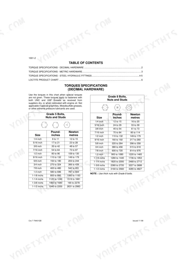
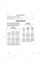
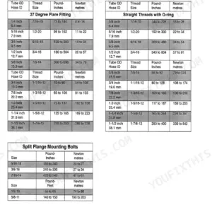
| General | Standard Torque Specifications and Loctite Product Chart (Torque Specifications - Decimal Hardware, Torque Specifications - Metric Hardware, Torque Specifications - Steel Hydraulic Fittings) | |
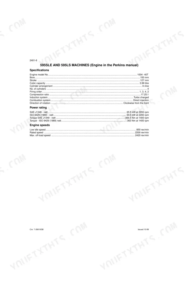
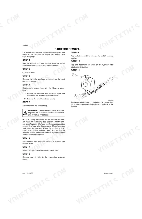
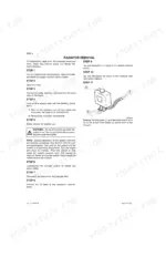
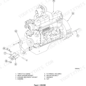
| Engine | Engine and Radiator Removal and Installation, Engine Removal | |
| Fuel System | Fuel Tank and Lines, Fuel Injection Pump, Fuel Filters, And Fuel System Specifications | |
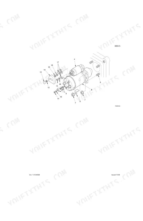
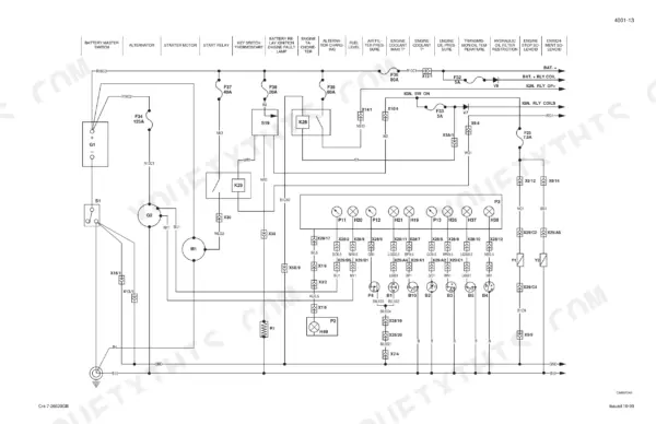
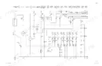
| Electrical | Electrical Schematic, Battery, Starter Motor, Removal and Installation of Electrical Components, Alternator, Loader and Backhoe Calibration | |
| Steering | Removal and Installation of Steering Components, Steering Specifications, Pressure Checks and Troubleshooting, Steering Control Valve, Steering Cylinder, Front Axle | |
| Power Train | Removal and Installation of Power Train Components, Transmission Specifications, Pressure Checks and Troubleshooting, Wheels and Tyres, Gear Box, Rear Axle-Four Whell Steer | |
| Brakes | Removal and Installation of Brake Components, Disassembly and Assembly of Brake Components | |
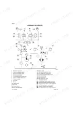
| Hydraulics | Removal and Installation of Hydraulic Components, Hydraulic Specifications, Troubleshooting and Pressure Checks, Cleaning the Hydraulic System, Hydraulic Pump and Unloader Valve | |
| Mounted Equipment | Pedals and Levers, Loader, Cab and ROPS, Backhoe, Seat and Seat Belt, Removal and Installation of Components |
Quick Reference Specifications
| Specification | Value | Page |
|---|---|---|
| Depressurizing hydraulic system (control valves method) | Remove hydraulic reservoir cap, place special wrench on nut of each loader and backhoe control valve section, turn wrench as far as it will go from top to bottom, repeat for each section, refit hydraulic reservoir cap. | p. 354 |
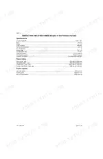
| Engine mounting bolts torque | M16 280 Nm | p. 19 |
| Engine mounting nuts torque | M10 48 Nm | p. 19 |
| Engine Oil Capacity (with filter replacement) | 10.7 litres | p. 13 |
| Hydraulic Reservoir Filling Capacity (with filter replacement) | 45 litres | p. 13 |
| Transmission Total System Capacity | 19 litres | p. 13 |
| Front Axle Drive Axle Oil Capacity | 15 L | p. 209 |
| Orbitrol Steering Unit Relief Valve Setting | 170 to 175 bar | p. 182 |
| Engine Mounting Bolts Torque (M16) | 280 Nm | p. 19 |
| Loader Bucket Cylinder Stroke | 515 mm | p. 400 |
| Alternator Maximum DC Output | 55 A | p. 143 |
| Brake Pedal Free Travel | 0,5 to 1,3 mm | p. 475 |
Case 595SLE, 595LSP Common Problems This Manual Covers
Case 595SLE hydraulic pump losing pressure under load, boom lift slows during digging
Check pump outlet pressure at the test port in the hydraulics troubleshooting section on page 343. Verify front pump output does not exceed the 230 bar maximum continuous pressure rating on page 380. If pressure reads low, depressurize the system per the control valve procedure on page 354, then refer to the cleaning hydraulic system procedure starting on page 371.
Manual Section: Hydraulics p. 380Steering wheel turns hard or requires excessive effort at low engine speed
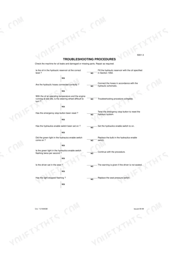
Check oil level and hose connections following the steering troubleshooting procedures. Test the Orbitrol steering unit relief valve setting; it should read 170 to 175 bar as specified on page 182. If pressure falls outside that range, adjust the relief valve and check for internal leakage past the piston packing before road testing again.
Manual Section: SteeringTransmission loses power or hesitates when changing gears under heavy load on grades
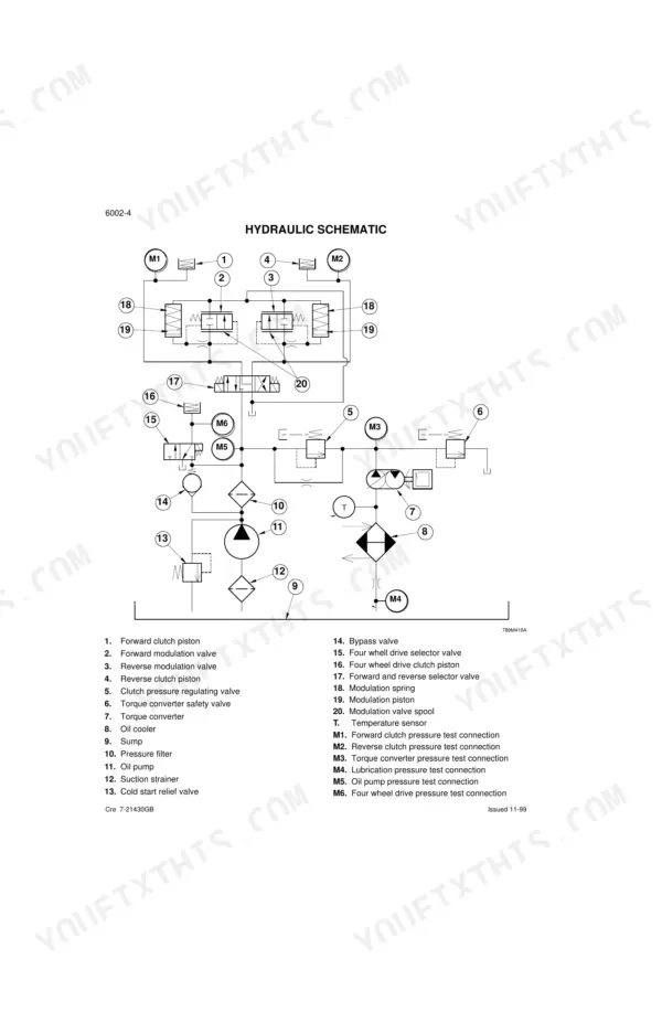
Check the power train hydraulic schematic to trace the clutch pressure circuit before pulling the valve body. Confirm the transmission holds its full 19 litre system capacity listed on page 13, since a low level alone causes hesitation on shifts. Bleed air from the circuit and retest under load once the level is corrected.
Manual Section: Power TrainAlternator warning light stays on or battery won't hold a charge overnight
Check the electrical schematic starting on page 47 to trace the charging circuit before replacing parts. Measure alternator output directly at the output terminal and compare it against the 55 amp maximum DC output rating specified on page 143. If output reads low, inspect the cable connections and rotor field circuit, then rerun the calibration procedure.
Manual Section: Electrical p. 143Loader bucket cylinder leaks oil past the seals or fails to reach full extension
Depressurize the hydraulic system first by placing the special wrench on each control valve section nut and turning it fully from top to bottom, following the procedure on page 354. Measure cylinder stroke against the 515 mm specification on page 400. If stroke falls short, replace the rod seals and inspect the barrel for scoring before reassembly.
Manual Section: Hydraulics p. 400Brake pedal feels spongy underfoot and travels too far before the brakes engage
Measure brake pedal free travel with a straightedge; it should fall between 0,5 and 1,3 mm as specified on page 475. If travel exceeds that range, adjust the pedal linkage and bleed the circuit to remove trapped air. Inspect the master cylinder pushrod for wear if travel keeps drifting after adjustment.
Manual Section: Mounted/Equipment p. 475Frequently Asked Questions
How to reset the hydraulic system on Case 595SLE 595LSP?
To reset the hydraulic system, turn the starter switch key to "On" and press the hydraulic enable switch. For 595SLE, place the loader control lever in float position and operate it from left to right several times to release hydraulic pressure. For 595LSP, press the loader or backhoe attachment selector button to gain control. p. 355
What are the torque specs for the engine bolts on Case 595SLE 595LSP?
The engine mounting bolts (M16) should be torqued to 280 Nm. Setscrews for the engine lift bracket require a torque of 44 Nm. p. 19
How to interpret error codes on Case 595SLE 595LSP?
The manual does not list specific alphanumeric error codes like E01 or E02. Instead, it provides troubleshooting procedures based on fault warning alarms (e.g., single beep, four beeps) and observed symptoms, guiding the user through diagnostic steps and pressure checks. p. 720
How to reset the electronic control unit on Case 595SLE 595LSP?
To interact with the Hydraulic Management Unit (HMU), which is an electronic control unit, a diagnostic terminal can be plugged into the 5 pin test point. If the screen is blank, pressing 'Shift then ?' will initiate the terminal to the front screen. A general system reset can also be performed by twisting the emergency stop button. p. 158
What format is this Case 595SLE manual in?
Immediate download of the complete 819-page searchable Service Manual. Access it on any device, from a laptop at your desk to a phone in the field.
Can I print pages of this Case 595SLE manual for my own shop?
Yes. Many mechanics print the section they need for their own shop and bring it to the bench.
Is the hydraulic system diagrammed in this Case 595SLE manual?
Yes, complete hydraulic schematics with flow diagrams, valve configurations, and pressure specifications are included.










Reviews
There are no reviews yet.