

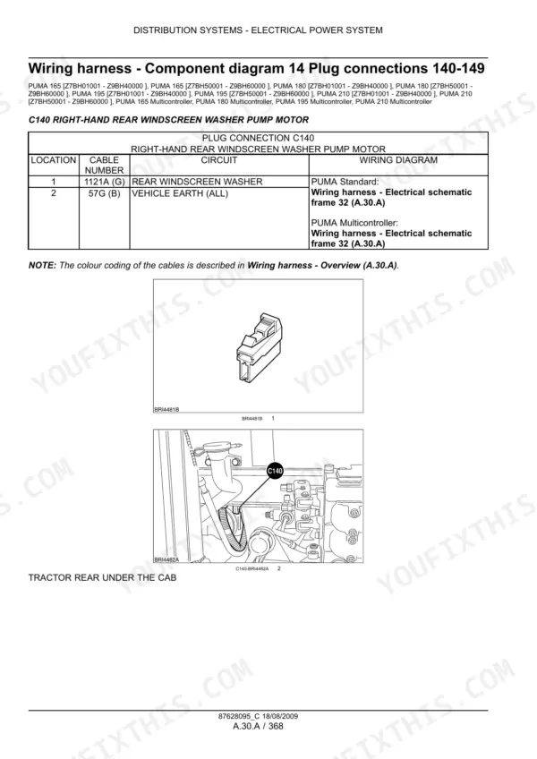
![Case IH Puma 165 service manual - Electrical Power System, PUMA 210 [Z7BH01001 - Z9BH40000 ], PUMA 210 [Z7BH50001 - Z9BH60000 ], PUMA 165](https://youfixthis.com/wp-content/uploads/2026/07/case-ih-puma-165-210-multicontroller-service-c98d0-page-364-600x848.webp "case-ih-puma-165-210-multicontroller-service-c98d0-page-364.webp")

![Case IH Puma 165 service manual - Electrical Power System, PUMA 210 [Z7BH01001 - Z9BH40000 ], PUMA 210 [Z7BH50001 - Z9BH60000 ], PUMA 165](https://youfixthis.com/wp-content/uploads/2026/07/case-ih-puma-165-210-multicontroller-service-c98d0-page-364-150x212.webp "case-ih-puma-165-210-multicontroller-service-c98d0-page-364.webp")
Part of the Case Repair Manuals.
This is the factory service manual Case IH dealers used on the Puma 165, 180, 195 and 210, in both standard and Multicontroller trim, built 2007 to 2011. It follows the Case IH system letters: A Distribution Systems for hydraulics and electrics, B Power Production for the engine, C Power Train, D Travelling for axles, brakes and steering, E Body and Structure, and H Working Arm for the hitch. The numbers in it are the real ones you test against: 150 l/min CCLS pump flow (120 l/min on the smaller variant), 210 bar system pressure, 230 bar lift cylinder safety valve, 3 bar transmission charge pressure. These are Tier 3 tractors with ECUs and a CAN bus, and the manual treats them that way, with fault diagnosis built around actual trouble codes instead of guesswork.
Complete the set for your Puma 165-210
- Operator Manual: Case IH Puma 165, 180, 195, 210 Operator Manual
- Operator Manual: Case IH Puma 140, 150, 165 Tractor Operator Manual
Other edition of this manual
- Case IH Puma 165, 180, 195, 210, 225 CVT Service Manual (84190392A, 12/2009) — Wiring Diagrams Original price was: $44.99.$19.99Current price is: $19.99.
What's Inside This Case IH Puma 165-210 Manual
| System | Pages | Key Topics |
|---|---|---|
| Hydraulic Power System | 20-358 | Pump Flow 150 or 120 l/min, System Pressure 210 Bar, Remote Valves, Lift Cylinder Safety Valve 230 Bar, Filters |
| Electrical Power System | 359-1047 | Battery and Charging, Static and Component Testing, Fuses and Relays, Component Location |
| Wiring Harnesses and Schematics | 1048-1502 | Wiring Diagrams, Harness Overviews, Connector Identification and Pinouts |
| Electronic Control Units | 1503-2091 | Control Unit Configuration, CAN Bus, Electronic Modules, Calibration |
| Power Production - Engine | 2092-2536 | Engine Removal and Overhaul, Fuel Injection, Cooling, Air Intake, Engine Electronics |
| Power Train | 2537-2685 | Transmission and Clutch, PTO, Charge Pressure 3 Bar Diagnosis, Calibration |
| Travelling - Axles, Brakes, Steering | 2686-3112 | Front and Rear Axles, Differential Lock, Brakes, Steering System |
| Body and Structure | 3113-3117 | Cab, Bodywork, ROPS, Panels |
| Working Arm | 3118-3248 | Rear Hitch, Three Point Linkage, Remote Valves, Front Loader |
Quick Reference Specifications
| Specification | Value | Page |
|---|---|---|
| Hydraulic pump flow | 150 l/min (39.6 US gpm) | p. 30 |
| Hydraulic system pressure (DR) | 210 bar | p. 30 |
| Hydraulic system pressure (FR) | 26 bar | p. 30 |
| Hydraulic pump flow | 120 l/min (31.7 US gpm) | p. 30 |
| Hydraulic system pressure (DR) | 210 bar | p. 31 |
| Hydraulic system pressure (FR) | 26 bar | p. 31 |
| Lifting cylinder safety valve pressure limit | 230 bar (3335.0 psi) | p. 38 |
| Lifting cylinder sizes | 80 mm, 90 mm, 100 mm | p. 41 |
| Charge pump pressure | 3 bar (44 lbf/in²) | p. 45 |
| Oil temperature switch threshold | 40 °C | p. 55 |
| Low charge pressure switch threshold | 0.75 bar (11 lbf/in²) | p. 56 |
| Charge pressure filter dump valve operating pressure | 6 bar (87 lbf/in²) | p. 56 |
| Charge pressure valve operating pressure (start) | 1 bar (14.5 lbf/in²) | p. 56 |
| Charge pressure valve operating pressure (limit) | 3 bar (44 lbf/in²) | p. 56 |
Case IH Puma 165-210 Common Problems This Manual Covers
Remote valves or loader feel weak, slow, or quit entirely under load
Distribution Systems - A gives the pressure and flow test procedure: run the engine at 1500 rev/min, tee in a 0 - 250 bar gauge, and compare against the 210 bar system spec and the 150 l/min (or 120 l/min variant) pump flow. It separates a worn pump from a stuck relief or a lazy Load Sensing signal.
Manual Section: DISTRIBUTION SYSTEMS - A p. 20Transmission fault light or low charge pressure warning, harsh or delayed shifts
Power Train - C covers charge circuit diagnosis with real thresholds: 3 bar normal charge pressure, warning switch at 0.75 bar, filter dump valve at 6 bar, oil temperature switch at 40 degrees C, tested at the 65 degree C operating temperature. Following the sequence tells you whether the pump, the filter, or a valve is at fault before you split anything.
Manual Section: POWER TRAIN - C p. 2537Rear hitch drops with a load, will not lift to full height, or creeps down overnight
Working Arm - H covers the hitch hydraulics, including the lifting cylinder safety valve set at 230 bar and the three cylinder sizes fitted to this range: 80, 90 and 100 mm. The section walks cylinder resealing, valve testing and linkage adjustment so you can pin down whether the leak is internal to the cylinder or in the control valve.
Manual Section: WORKING ARM - H p. 3118Intermittent electrical faults: gauges drop out, functions die and come back, no-start with no obvious cause
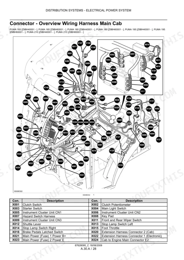
Distribution Systems - A carries the wiring schematics, connector views and ground point locations for the whole tractor. On these CAN bus machines most ghosts trace to a corroded ground, a backed-out connector pin or a chafed harness, and the schematics let you test each leg with a meter instead of swapping parts on a hunch.
Manual Section: DISTRIBUTION SYSTEMS - A p. 20Frequently Asked Questions
Does this manual cover the Puma 225 or the CVX models?
No, and I want to be straight about that. The applicability list on this book (document 87628095) names the Puma 165, 180, 195 and 210, standard and Multicontroller only. If you run a Puma 225 or any CVX, you need the separate CVX service manual. This one will still be wrong for your transmission even if the engine looks familiar.
My Multicontroller is throwing fault codes. Will this help me figure out what they mean?
Yes. These are Tier 3 tractors with real ECUs on a CAN bus, and the manual is written around diagnosing through the trouble codes rather than around them. It walks the electrical checks behind a code: the sensor, the wiring run, the connector and the ground point, so you can tell a dead sensor from a chafed harness before you buy anything.
Does it cover both the standard and Multicontroller versions?
Yes, both. The cover applicability lists each model twice: Puma 165 and 165 Multicontroller, and the same for the 180, 195 and 210. Where the two versions differ, mostly in armrest controls and the electronics behind them, the manual splits the procedure so you follow the right one.
Are the actual pressure test specs in here, or just remove-and-replace steps?
The specs are in here, which is the whole point of a factory book. Hydraulic pressure testing is done at 1500 rev/min with a 0 - 250 bar gauge, checking for 210 bar system pressure and a Load Sensing line that swings from 0 up to 210 plus or minus 5 bar. You get pass/fail numbers, not vague advice. p. 30
I have transmission warnings. Does the manual cover charge pressure diagnosis?
Yes, in the Power Train section. It gives the working numbers: 3 bar charge pump pressure, the low charge pressure switch tripping at 0.75 bar, the filter dump valve opening at 6 bar, and testing with the oil at its 65 degree C operating temperature. With those you can tell a lazy charge pump from a clogged filter in one afternoon. p. 30









