
Part of the Case Repair Manuals.
When the head comes off and the deck needs checking, the Case 6-590, 6T-590, 6TA-590 service manual PDF, factory number 7-67681, puts all 357 pages of original shop data for these six-cylinder diesel engines on your bench. Rebuild procedures take up most of the book: crankshaft reconditioning, valve guide and seat replacement, camshaft installation, and flywheel housing alignment, each ending with the measurements that tell you the part is fit to run. Separate turbocharger chapters handle the HX35W, from disassembly through wastegate calibration, and the fuel section walks through timing on both the CAV and Bosch VE injection pumps. Check deck flatness against the 0.075 mm overall warpage limit before you commit to resurfacing, then pull the short head bolts down to 90 Nm plus a 90 degree turn. Nobody wants to tear down a fresh rebuild twice. Bookmarked and keyword searchable, the PDF goes wherever the engine is, on a stand or in service.
What's Inside This Case 6-590, 6T-590, 6TA-590 Manual
| System | Pages | Key Topics |
|---|---|---|
| General | 4-11 | Standard Torque Specifications, Product Loctite Chart |
| Specification Details (6-590 Diesel Engine) | 12-25 | Run-In Instructions, Identification Marks, Cylinder Block Specifications, Piston and Ring Specifications, Crankshaft Specifications, Special Torques |
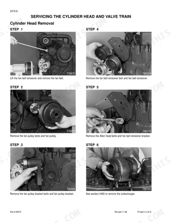
| Cylinder Head and Valve Train | 26-73 | Cylinder Head Removal, Valve Guide Replacement, Valve Seat Installation, Refacing Valves, Rocker Arm Assembly, Adjusting Valve Clearance |
| Cylinder Block (Crankshaft, Pistons, Rods, Sleeves, Camshaft, Bearings, Seals and Flywheel) | 74-159 | Engine Block Servicing, Cylinder Wall Inspection, Piston and Rod Removal, Crankshaft Reconditioning, Camshaft Installation, Flywheel Housing Alignment |
| Lubrication System (Oil Pan, Oil Pump, Oil Cooler and Oil Filter Housing) | 160-177 | Lubrication Flow Diagrams, Oil Pump Removal and Installation, Oil Pressure Relief Valve, Oil Cooler Service, Oil Pan Installation |
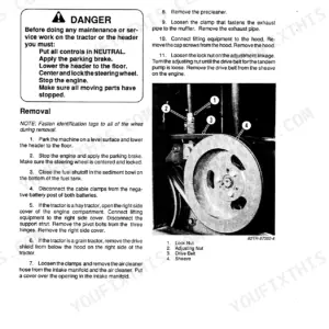
| Cooling System (Thermostat, Water Pump, Fan Pulley and Belt Tensioner) | 178-195 | Water Pump Service, Thermostat Replacement, Coolant Inlet Servicing, Fan Pulley Servicing, Belt Tensioner Servicing, Coolant Flow Diagrams |
| Turbocharger (6T-590 and 6TA-590) | 196-221 | Turbocharger Removal and Inspection, Disassembly and Assembly, Troubleshooting Guide, Wastegate Calibration |
| HX35W Turbocharger | 222-247 | Turbocharger Service, Wastegate Calibration, Cross Section Diagrams, Troubleshooting Guide |
| Fuel System and Filters | 248-265 | Fuel Filter Replacement, Lift Pump Service, Primer Pump Testing, Fuel Injection Pump Timing, Fuel Injector Maintenance |
| Fuel System | 266-357 | Fuel System and Filters, Cav Injection Pump (Pump Drive Gear, Timing Pin, Fuel Shutoff Solenoid, Primmer Pump and Pump Timing) |
Quick Reference Specifications
| Specification | Value | Page |
|---|---|---|
| Cylinder Head Bolts (Short) | 90 Nm Plus 90 Degrees | p. 26 |
| Cylinder Head Bolts (Long) | 120 Nm Plus 90 Degrees | p. 26 |
| Camshaft Retaining Bolts | 21 to 27 Nm | p. 20 |
| Cylinder Head Maximum Warpage | 0.010 mm in any 50 mm diameter area or more than 0.075 mm overall end to end or side to side | p. 28 |
| Maximum amount of material that can be removed during resurfacing | 1.0 mm | p. 28 |
| ID of Bushing Installed | 54.107 to 54.133 mm | p. 79 |
| Relief Valve Plug Torque | 80 Nm | p. 162 |
| Oil Pump Relief Valve Spring (2 Hole) Free Length | 55.83 mm | p. 162 |
| Adapter Connection Bolts | 20.5 Nm (181 lb inch) | p. 224 |
| Fuel injector line bracket bolts torque | 24 Nm | p. 255 |
| Lift pump output pressure (Diaphragm Type) | 21 kPa (3 PSI) Min. | p. 268 |
| Lift pump output pressure (Piston Type - In-line Injection Pumps) | 172 kPa (25 PSI) Min. | p. 268 |
Case 6-590, 6T-590, 6TA-590 Common Problems This Manual Covers
Blue smoke at idle and oil pooling in the intake pipe after turbocharger replacement
Check the turbo oil drain hose for collapse, kinks, or internal coking; a restricted drain pushes oil past the seals into the intake. Inspect the drain gasket and replace hardened hoses and clamps. On an HX35W unit, torque the adapter connection bolts to 20.5 Nm (181 lb inch), listed on page 224.
Manual Section: HX35W Turbocharger p. 224Heavy blow by from the breather tube, oil consumption climbing between service intervals
Test crankcase pressure with a manometer before pulling the engine apart. If pressure is over the limit, remove the pistons and measure each bore; the maximum service limit is 102.116 mm, listed on page 15. Check for taper, out of round wear, and dusting scratches, then rebore or sleeve any cylinder past the limit.
Manual Section: Cylinder Block (Crankshaft, Pistons, Rods, Sleeves, Camshaft, Bearings, Seals and Flywheel) p. 74Loud tappet clatter at idle and rough running, valve lash never set after rebuild
Adjust valve lash with the engine cold: 0.254 mm intake and 0.508 mm exhaust, the clearances listed on page 21. Follow the adjustment procedure in the valve train service pages starting at page 31. While the cover is off, verify rocker arm pedestal bolts are at 21 to 27 Nm and inspect pushrod ends for galling.
Manual Section: Cylinder Head and Valve Train p. 31Frequently Asked Questions
What are the torque specifications for the 6T-590 engine cylinder head bolts?
The cylinder head bolts for the 6-590 engine are tightened in three stages. First, tighten the bolts to 41 Nm, then to 90 Nm. Finally, tighten the long bolts (6, 3, 14, 11, 19, and 22) to 120 Nm, followed by an additional 90-degree turn for each bolt. p. 63
What are the torque specifications for the fuel injector retaining nut on the 6-590 engine?
The injector retaining nut must be tightened to a torque of 55 to 60 Nm. p. 68
How do you fix case 6T-590 low oil pressure light at idle, gauge drops after engine reaches operating temperature?
Remove the oil filter head relief valve and measure the spring free length: a two hole relief valve spring should be 55.83 mm free with a 449 kPa opening pressure, listed on page 162. Replace any collapsed spring, check the plunger for scoring, and torque the relief valve plug to 80 Nm on reassembly. p. 162
How do you fix engine cranks but will not start after fuel filter change, dies as soon as primer stops?
Bleed the fuel system, then test lift pump output pressure against the specs on page 268: a diaphragm type pump must make at least 21 kPa (3 PSI). Replace the pump if it falls short. Check every fitting and filter seal on the suction side for air leaks before condemning the injection pump. p. 268
What exactly do I receive with this Case 6-590 Service Manual?
Straight to your device: 357 pages of searchable Service Manual, downloadable the moment payment goes through.
Can I print pages of this Case 6-590 manual for my own shop?
Yes. It prints from any PDF reader, so run off the pages you need for your own repair work.










Reviews
There are no reviews yet.