
Part of the Case Repair Manuals.
Looking for a Case 980 service manual PDF that actually came from the factory? All 513 pages of this Case 980 Excavator Service Manual (OEM #9-73476) take you from engine block to turntable bearing. Inside: full hydraulic schematics with relief valve pressure settings, electrical diagrams for the starter and charging circuits, and page after page of teardown procedures covering the cylinder head, crankshaft, Bosch injection pump, and Roosa Master injectors. You also get a real troubleshooting section, so you can diagnose before you pull a single bolt. Set the connecting rod bolts at 95 to 105 ft. lbs., torque the crankshaft nut to 125 to 135, and confirm fuel system pressure holds 20 to 30 PSI. Forum guesses won't rebuild your final drive. This bookmarked PDF opens on any device; take your tablet out to the machine and start wrenching.
What's Inside This Case 980 Manual
| System | Pages | Key Topics |
|---|---|---|
| General Information | 2-3 | Engine, Fuel System, Hydraulics, Track and Suspension, Power Train |
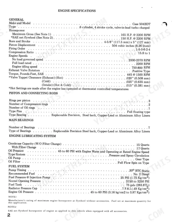
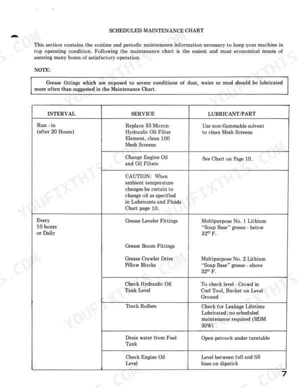
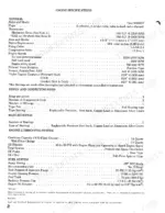
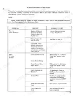
| Series - General | 4-39 | Engine Specifications, Overall Unit Dimensions, Track Dimensions, Electrical System, Hydraulic Valves Pressure Settings, Scheduled Maintenance Chart |
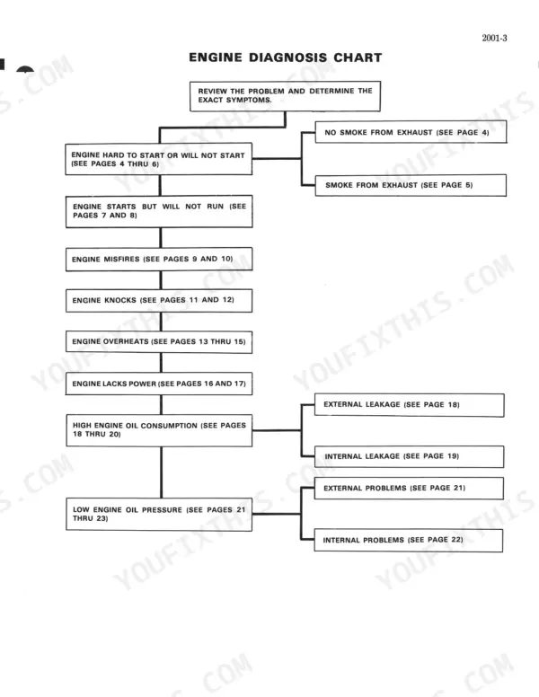
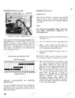
| Series - Engine | 40-223 | Engine Diagnosis, Engine Tuneup, Cylinder Head, Valve Train and Camshaft, Cylinder Block, Sleeves, Pistons and Rods, Crankshaft |
| Series - Fuel System | 224-271 | Fuel System and Filters, Robert Bosch Fuel Injection Pump, Roosa Master Fuel Injectors |
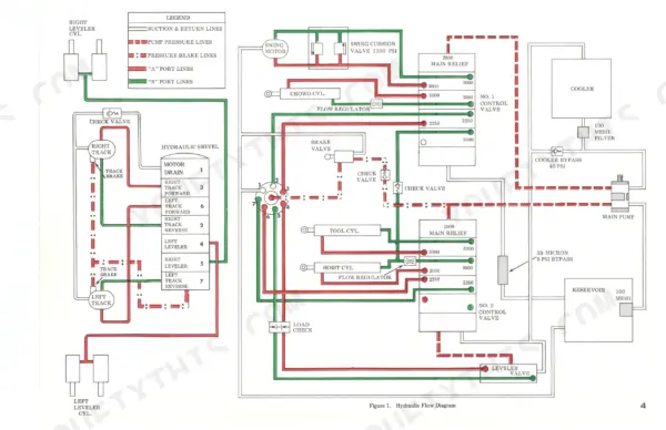
| Series - Hydraulics | 272-393 | Hydraulic Specifications, Diagram, Trouble Shooting, And Adjustments, Hydraulic Pump and Motors, Hydraulic Control Valves, Relief Valves, Check Valves and Swivel |
| Series - Track and Suspension | 394-407 | Undercarriage, Track Links, Track Rollers, Idler Wheel, Track Adjustment Cylinder |
| Series - Power Train | 408-463 | Final Drive Transmission, Swing Reducer and Brake, Turntable Bearing |
| Series - Brakes | 464-475 | Track Drive Brake |
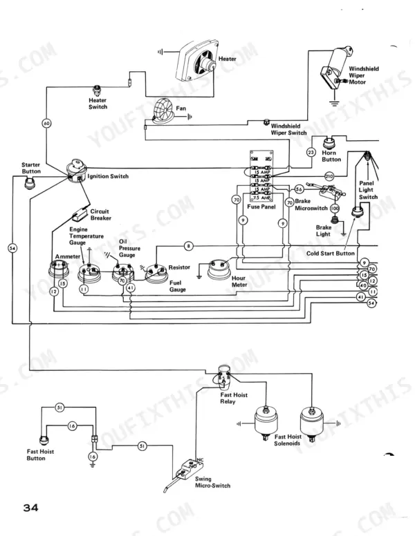
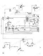
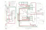
| Series - Electrical | 476-513 | Starter Circuit, Charging Circuit, Starter, Alternator, Electrical Schematic |
Quick Reference Specifications
| Specification | Value | Page |
|---|---|---|
| Camshaft nut | 95 to 105 ft. lbs. | p. 37 |
| Connecting rod bolts | 95 to 105 ft. lbs. | p. 37 |
| Fuel system operating pressure | 20 to 30 PSI | p. 225 |
| Bearing cap capscrew torque | 35 ft. lbs. | p. 379 |
| Torque for mounting bolts | 200 ft./lbs. | p. 403 |
| Torque for bushing assembly bolts | 40 ft./lbs. | p. 403 |
| Cylinder Head Bolt Torque | 210 ft. lbs. | p. 113 |
| Main Bearing Cap Bolt Torque | 155 ft. lbs. | p. 167 |
| Hydraulic Pump Rating | 39 GPM @ 2000 RPM | p. 275 |
| Alternator Output | 35 Amp | p. 11 |
Case 980 Common Problems This Manual Covers
Engine cranks slowly or will not turn over after sitting overnight in cold weather
Test battery capacity and load before condemning the starter. Clean and tighten ground cables, then run the starter motor no-load test in the electrical section starting on page 476. With the engine running, verify the 35 Amp alternator is charging per page 11; replace the starter solenoid only after the relay checks good.
Manual Section: Starter Electrical Circuit p. 476Tracks derail on turns and rollers wear out fast on rocky ground
Measure track sag and adjust tension through the track adjustment cylinder, following the undercarriage procedures that begin on page 394. Inspect rollers and idlers for flat spots and leaking seals. When you reinstall a roller, torque the mounting bolts to 200 ft. lbs. per page 403, then recheck tension after one shift.
Manual Section: Track and Suspension p. 394Engine starts but stalls under load or loses power intermittently in wet weather
Drain water and sediment from the fuel tank, then replace both fuel filters and bleed the system using the procedure starting on page 224. Test fuel system operating pressure; it should hold 20 to 30 PSI with the preliminary filter per page 225. Low pressure after new filters points to a weak transfer pump.
Manual Section: Fuel System and Filters p. 224Engine runs hot and coolant temperature gauge climbs during long trenching passes in summer
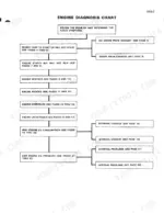
Clean the radiator fins with compressed air from the fan side and check coolant level cold. Work through the overheating checks in the engine troubleshooting procedures. Inspect fan belt tension and the water pump; if you pull the fan, reuse the water pump and fan shaft torque values from the engine specification tables rather than guessing.
Manual Section: Engine DiagnosisFrequently Asked Questions
What are the replacement specifications for hydraulic filters?
The hydraulic oil filter element should be replaced every 500 hours of operation. Additionally, the mesh screens must be cleaned at this interval. p. 14
What are the replacement specifications for fuel filters?
Fuel filters should be replaced every 500 hours of operation or when engine power loss is indicated. When replacing, ensure the filter head and engine area are clean, and use a clamp-type filter wrench for removal. p. 225
What is the torque specification for the cylinder head bolts?
The cylinder head bolts must be torqued in three steps to a final value of 210 ft. lbs. The torque sequence is provided in the manual. p. 113
How do you fix case 980 excavator loses hydraulic power under load, bucket and boom stall on hard digging?
Check hydraulic oil level and run a stall check before pulling the pump. Flowmeter test the pump against its 39 GPM at 2000 RPM rating on page 275. If flow falls well short, inspect the suction line for restriction and flush the system before installing a new pump. p. 275
How quickly can I access this Case 980 manual after buying?
This is a 513-page scanned PDF ready for immediate download. Works on any device, so pull it up on your phone while you're under the hood. No shipping, no waiting.
Am I able to print pages from this Case 980 manual?
Yes. Print the pages or sections you need for your own shop use. Any standard printer works.
Does this Case 980 Service Manual have electrical diagrams?
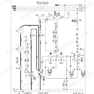
Yes, full electrical schematics are included with wire colors, connector locations, and circuit descriptions. See page 124 for an example.









Reviews
There are no reviews yet.