
Part of the Case Repair Manuals.
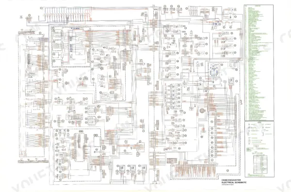
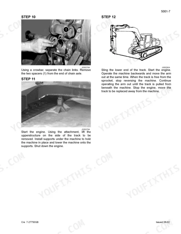
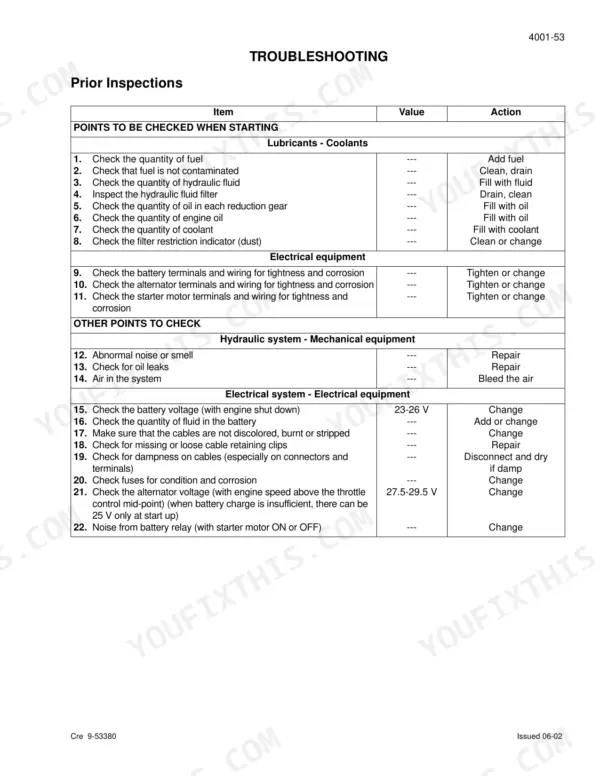
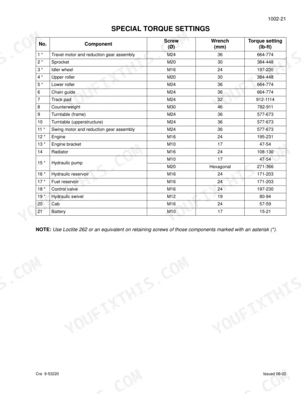
Your CX290 is dead in the dirt and the dealer wants three weeks? This 607-page Case CX290 Service Manual PDF puts the full factory playbook for the Crawler Excavator on your screen tonight. Inside: complete wiring diagrams and hydraulic schematics, a full electronic troubleshooting section, pressure testing and relief valve setting procedures, plus teardown steps for the Kawasaki main pump, swing motor, control valve, and every attachment cylinder. Undercarriage wear limits for sprockets, idlers, and rollers are all here too. Torque the engine retaining screws to 214 ± 18 lb-ft, and check that each 12-volt battery still cranks 800 amps cold before you blame the starter. No more chasing electrical gremlins with forum guesses. Bookmarked with a full text layer: search any spec, jump straight to any system, and get back in the seat.
What's Inside This Case CX290 Manual
| System | Pages | Key Topics |
|---|---|---|
| General | 6-37 | Safety Precautions (Wiring Diagrams) |
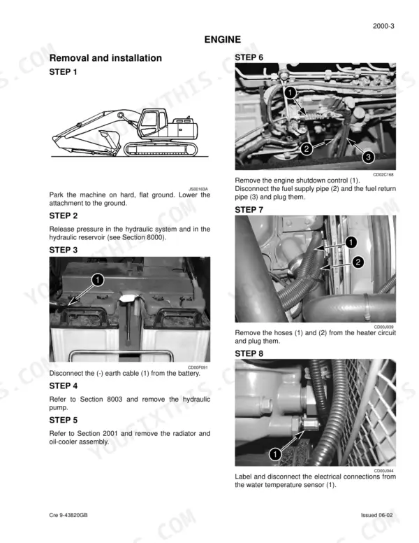
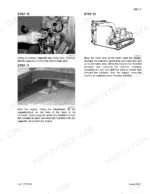
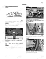
| Engine | 38-49 | Engine Removal, Engine Installation, Radiator, Oil-Cooler |
| Fuel | 50-55 | Fuel Tank, Fuel Engine System |
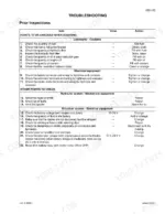
| Electrical | 56-143 | Electrical System, Electronic Troubleshooting, Batteries, Booster Battery, Control Boxes |
| Undercarriage | 144-197 | Tracks, Rollers, Sprocket, Idler Wheel, Tension Shock Absorber |
| Drive Train | 198-235 | Drive Motor, Swing Reduction Gear, Travel Reduction Gear |
| Pressure Release, Decontamination, and Vacuum Pump | 236-245 | Hydraulic System Pressure Release, Decontamination, Vacuum Pump Installation, Bleeding Air |
| Hydraulic Pressure Specifications and Troubleshooting | 246-271 | Hydraulic Pressure Settings, Troubleshooting, Pressure Testing, Pilot System Relief |
| Hydraulic Reservoir and Main Pump | 272-287 | Hydraulic Reservoir Removal, Main Hydraulic Pump Removal, Pilot Pump Removal, Pump Coupling |
| Main Control Valve and Attachment Cylinders | 288-313 | Main Control Valve Removal, Boom Cylinder, Dipper Cylinder, Bucket Cylinder |
| Hydraulic Swivel and Pilot Function Blocks | 314-345 | Hydraulic Swivel, Travel Pedal Block, Control Levers, Cushion Control Valve, Solenoid Valve Block |
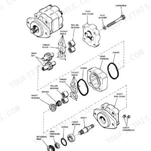
| Hydraulic Pump and Control Valve Disassembly | 346-379 | Kawasaki Hydraulic Pump Disassembly, Control Valve Disassembly, Spool Assembly, Anti-Drift Valve |
| Attachment Cylinders and Valves | 380-456 | Attachment Cylinder Disassembly, Anti-Hose Burst Valve, Cushion Control Valve, Pilot Function Blocks |
| Hydraulic Swivel, Swing Motor, and Functions | 457-531 | Hydraulic Swivel, Swing Hydraulic Motor, Swing Circuit, Free Swing Operation, Boom Raising Circuit |
| Upperstructure | 532-605 | Turntable, Counterweight, Boom, Dipper, Bucket, Cab, Air Conditioner |
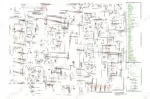
| Hydraulic and Electrical Schematics | 606-607 | Hydraulic Schematics, Electrical Schematics |
Quick Reference Specifications
| Specification | Value | Page |
|---|---|---|
| Voltage of each battery | 12 volts | p. 20 |
| Capacity | 112 Ah | p. 20 |
| Upper roller capacity | 8.08 to 8.25 oz | p. 20 |
| Lower roller capacity | 9.24 oz | p. 20 |
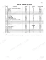
| Retaining screw of the engine | 214 ± 18 lb-ft | p. 35 |
| Fuse 20 A; Fuel filler pump | 20 A | p. 67 |
| Current in mA (H Mode Max) | 415 mA | p. 125 |
| Current in mA (H Mode Min) | 305 mA | p. 125 |
| Engine Oil Capacity | 6.3 gallons | p. 20 |
| Engine Cooling Circuit Capacity | 7.6 gallons | p. 20 |
| Fuel Reservoir Capacity | 89.8 gallons | p. 20 |
| Hydraulic Fluid Reservoir Capacity | 31.7 gallons | p. 20 |
Case CX290 Common Problems This Manual Covers
Case CX290 cranks but will not start, VP44 fault codes F367 through F377 on the monitor
Check battery condition first: each 12 volt battery must deliver 800 A cold cranking at 1.4°F, listed on page 20. Test for air in the fuel system and replace a clogged fuel filter. Then follow the diagnostic mode and error code procedures starting, inspecting harness and ECM connectors for loose or corroded pins.
Manual Section: Electrical and Electronic Circuit TroubleshootingHydraulic functions slow and weak, boom hesitates and digging force drops once the oil warms up
Verify hydraulic reservoir level; the system holds 31.7 gallons. Test main relief pressure against the 4975 ± 43 psi standard on page 21, following the pressure testing procedures that start on page 246. If pressure is low, adjust the relief valve. If the oil is aerated or contaminated, bleed and decontaminate the system per page 236.
Manual Section: Hydraulic Pressure Setting and Troubleshooting p. 246Engine overheats under load, coolant gauge climbs into the red during heavy digging cycles
Check coolant level cold; the cooling circuit holds 7.6 gallons. Inspect the radiator core for packed mud and clean it with low pressure air from the fan side. Test the thermostat in heated water: it must start opening at 180°F and stand fully open at 207°F, per page 45. Replace any collapsed or soft radiator hoses while the system is drained.
Manual Section: Radiator and Oil-Cooler p. 45Intermittent shutdown and random electrical faults, machine dies then restarts with no clear pattern
Inspect harness routing and connector terminals before replacing parts; wiggle test each connector with the engine running. Check the main fuses on page 63: the 65 A main fuse feeds circuits F3 to F10 and F13 to F20. Clean the battery terminals and torque the battery retaining screws to 15-21 lb-ft, shown on page 33.
Manual Section: Electrical and Electronic Circuit Troubleshooting p. 63Track noise and vibration when traveling, rollers squeal and the track jumps on the sprocket
Measure lower roller tread diameter: standard is 7.08 inches with a wear limit of 6.69 inches, listed on page 27. Replace any roller past the limit and check the sprocket teeth for hooking. Adjust track tension using the procedure in the tracks section starting on page 144, then road test and listen for final drive whine.
Manual Section: Upper and Lower Rollers p. 27Frequently Asked Questions
How do I reset the monitor/service display on a Case CX290?
To erase data in the machine history mode (screens HR1 to HR12), press the work mode switch for 10 seconds. For diagnostic data in CHK5 and DIAG2, scroll to the respective screen and press the work mode switch for 10 seconds until the buzzer sounds, then turn the key switch OFF. p. 101
How do I clear diagnostic or engine fault codes on a Case CX290?
To erase failure codes and hourmeter data in screens DIAG2 and DIAG3, press the work mode switch for 10 seconds. For DIAG5, scroll to the screen and press the work mode switch for 10 seconds until the buzzer sounds, then turn the key switch OFF. p. 96
How do I enter the diagnostic mode on a Case CX290?
To enter the diagnostic mode, press the Travel and Work mode switches simultaneously for 3 seconds while the starter motor switch is in the 'ON' position. You can then scroll between the CHK, DIAG, HR, and RST1 screens using the Auto mode switch. p. 91
What is the torque specification for the engine retaining screws on a Case CX290?
The retaining screws for the engine must be tightened to a torque of 214 ± 18 lb-ft. p. 39
What is the capacity of the hydraulic fluid reservoir on a Case CX290?
The hydraulic fluid reservoir capacity is 31.7 gallons. p. 20
Is this Case CX290 manual a PDF I download?
A single searchable PDF file of 607 pages, downloadable right after payment. Nothing ships, nothing waits in the mail.
Am I able to print pages from this Case CX290 manual?
Yes. Many mechanics print the section they need for their own shop and bring it to the bench.









Reviews
There are no reviews yet.