
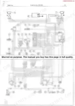
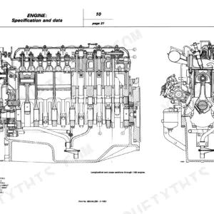
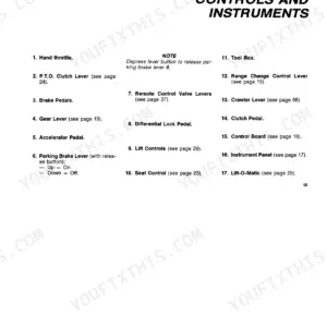
Fiat's factory service manual 603.54.194R takes the 1977 480, 500, 540 and 640 tractors apart on paper, covering all eight variants (two-wheel drive and DT four-wheel drive) across 372 pages; if you searched for a Fiat 500 service manual PDF, this is the book the dealer shop worked from. Hydraulic lift schematics trace the position control and draft control circuits behind the three-point linkage, while the C.A.V. injection pump section runs from teardown through bench calibration and ends in a trouble-shooting chart. A full wiring diagram backs up alternator bench-test data and starting motor service instructions. Set the injectors to 175 kg/cm² (2485 p.s.i.) and confirm the priming pump moves 100 liters per hour before you condemn the injection pump. Nobody within an hour can answer a bevel gear question at 9 p.m. Bookmarks and a live text layer put the section you need two taps away, so your weather window stays yours.
What's Inside This Fiat 480–640 / DT Manual
| System | Pages | Key Topics |
|---|---|---|
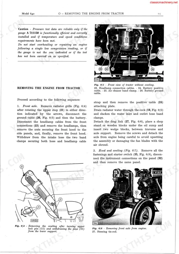
| Specifications - Removal Installation | 11-18 | Description, Specifications, Test Rig Data, Fault-Finding in Case of Poor Engine Performance, Removing the Engine From Tractor, Disassembly and Reassembly, Installation |
| Crankcase - Cylinder Head - Oil Sump | 19-24 | Crankcase and Cylinder Liners, Checking and Cleaning the Crankcase, Cylinder Liner Re-Boring and Replacement, Cylinder Head, Oil Sump |
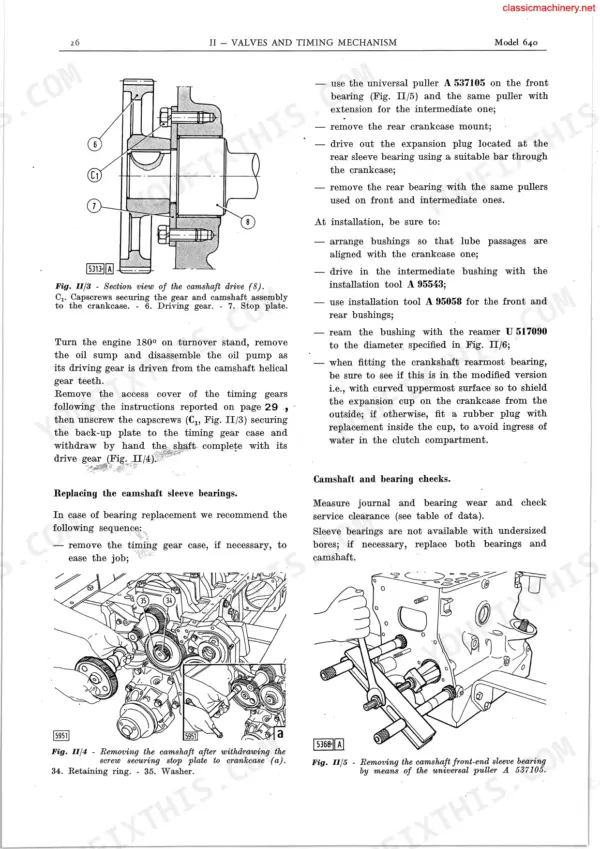
| Valves and Timing Mechanism | 25-32 | General, Timing Data, Camshaft, Valves and Their Guides and Springs, Valve Gap Adjustment, Tappets, Push-Rod and Rocker Arms, Timing Gears and Case |
| Crank Gear Assembly | 33-44 | General, Crankshaft, Crankshaft Bearings, Pistons and Rings, Connecting Rods, Engine Flywheel, Engine Vibration Damper |
| Fuel System | 45-78 | Specifications, Air Supply, Air Cleaner, Fuel Supply, Fuel Tank, Fuel Priming Pump, Fuel Filters, Fuel System Bleeding |
| Lubrication | 79-82 | General, Oil Pump, Oil Filter, Low Oil Pressure Warning Light, Engine Lubrication Diagram, Engine Lube Schedule and Capacities |
| Cooling | 83-88 | General, Water Pump, Radiator, Thermostat, Replacing the Fan and Alternator Drive Belts, Fan, Water Temperature Gauge |
| Fits and Tolerances - Torque Specifications - Service Tools | 89-98 | Size of New Parts and Wear Limits for the Engine: Crankcase Main Bearing Bore Diameters, Standard Piston Sizes with Oversizes and Piston-To-Liner Clearance, Small End Bushing Bore, Crankshaft Penultimate Journal Length and End Float, Timing Idler Gear Axle Diameter, Plus the Service Tool Numbers |
| Power Train | 99-112 | Description - Specifications - Lubrication (Transmission Ratios, Performance, Weight and Consumption Data, Lubricants - Dimensions) |
| Transmission | 113-122 | 8-Speed Transmission, Removing the 8-Speed Transmission, Dismantling the 8-Speed Transmission, Inspection, 8-Speed Transmission Assembly, Transmission Installation |
| Bevel Gear and Differential | 123-130 | Description - Removal - Disassembly, Inspection, Bevel Gear and Differential Assembly, Bevel Gear Setting |
| Brakes | 131-132 | Dry Contracting Band Brakes Acting on Two Drums Keyed to the Differential Axle Shafts, Mechanically Controlled by Independent Service Pedals; Disassembly, Inspection, Assembly and Adjustment, With the Final Drive Removed First |
| Final Drives and Rear Wheels | 133-136 | Final Drives Bolted to the Sides of the Rear Transmission, Each Carrying a Single-Reduction Spur Gear Train; Removal, Disassembly, Inspection and Assembly Together with the Rear Wheels |
| Front Axle and Steering | 137-144 | Steering Box, Removal - Disassembly, Inspection - Assembly, Steering Box Adjustment, Front Axle and Steering Wheels (Description, Overhaul, Front Axle Checks) |
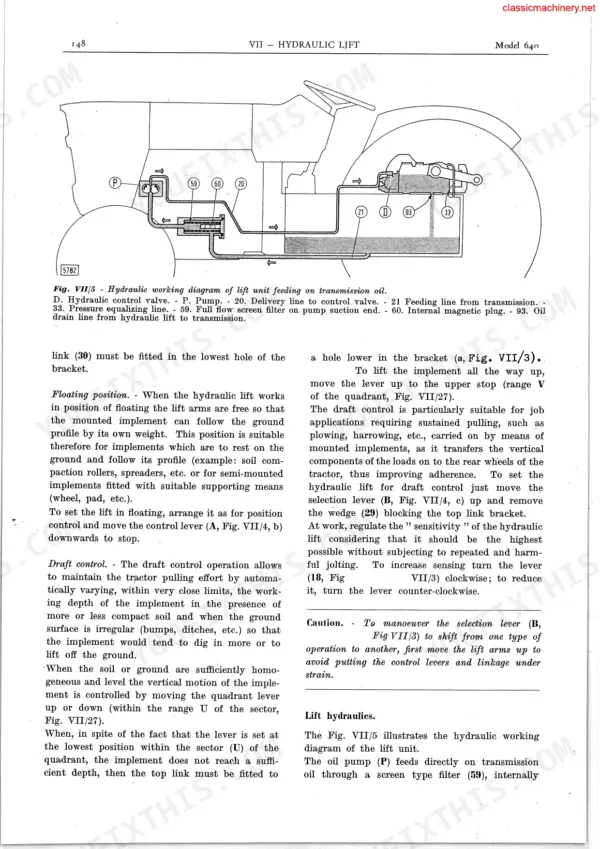
| Hydraulic Lift Unit | 145-168 | General, Specifications, Hydraulic Lift, Lift Hydraulics, Mechanics of the Hydraulic Lift Position Control Operation, Mechanics of the Draft Control Operation |
| Power Take Off - Belt Pulley | 169-186 | Power Take-Off, Overhauling, Belt Pulley, Bevel Gear Setting |
| Electrical System | 187-209 | Description and Operation, Charging Circuit and Self-Rectifying Current Generator (Nominal Voltage, Rotation, Statoric Phase Resistance), Starting Circuit and Magnetic Switch Testing, Headlamps and Lighting Circuit Protection, Trouble Location and Remedies with Possible Causes |
| Appendix - Engine (Models 640, 480, 500, 540) | 210-276 | Bosch Injection Pump Calibration, Engine Performance Tests, Fuel System Bleeding, Lubrication Schedules, Engine Specifications |
| Appendix - Transmission (Models 640, 480, 500, 540) | 277-312 | Transmission Ratios, Power Train Attachments, Subsidiary Speed Reduction Unit, Front Wheel Drive, Steering Box Overhaul |
| Appendix - Electrical System (Models 480, 500, 540) | 313-340 | Battery Specifications, Starting Motor Data, Electrical System Wiring, Troubleshooting Charts, Accessory Equipment |
| Appendix - Hydraulic Lift and Power Steering (Models 500, 540) | 341-372 | Hydraulic Lift Unit Specifications, Power Steering Cylinder Installation, Hydraulic Pump Overhaul, Control Valve Adjustments, Troubleshooting |
Quick Reference Specifications
| Specification | Value | Page |
|---|---|---|
| All Models | ||
| Fuel priming pump min. output | 100 liters/hr | p. 47 |
| Fuel priming pump pressure head | 5 mm | p. 47 |
| corresponding output with an oil temperature of 50-60°C (122-140°F) and 150 kg/cm² (2133 p.s.i.) pressure | 21.8 liters/1' (4.8 GPM) | p. 146 |
| Output on test bench at 1445 r.p.m. and at pressure 130-140 kg/sq.cm (1849 to 1991 p.s.i.) - new or overhauled pump | 13.6 lts/min (3 GPM) | p. 146 |
| Thickness of P.T.O. and transmission clutch friction discs (Ferodo) | 8.500 - 8.900 mm | p. 173 |
| Spring pressure on brushes (not worn) | 0.8 to 1.1 kg (1.8 to 2.4 lb) | p. 198 |
| Mica undercutting | 0.8 mm (0.032 in) | p. 198 |
| Screw, front wheel | 26.5 Kgm (191.5 ft.lb) | p. 299 |
| Thickness of P.T.O. and transmission clutch friction discs | 8.580 - 9.400 mm | p. 297 |
| 640 | ||
| Engine Oil Capacity (Model 640) | 10.5 kg | p. 82 |
| 480 | ||
| Engine Oil Capacity (Model 480) | 6.8 kg | p. 276 |
| 500 | ||
| Engine Oil Capacity (Model 500) | 6.8 kg | p. 276 |
Fiat 480–640 / DT Common Problems This Manual Covers
Fiat 640 hydraulic lift won't raise, three-point hitch control lever stiff and hard to move
Drain and inspect the hydraulic oil first; contaminated oil sticks the control valve and linkage. Bench-test the pump using the figures on page 146: a good pump delivers 21.8 liters per minute at 150 kg/cm2 (2133 psi) with oil at 50-60 C. Anything under 10.1 liters per minute at 1445 rpm means replace the pump before planting season.
Manual Section: Hydraulic Lift Unit p. 146Engine cranks strong but won't fire, grey smoke and long cranking before it catches
Bleed the fuel system at the filters and injection pump before condemning parts; air trapped after a filter change mimics a dead pump. Test transfer pump internal pressure next: 0.8 to 1.4 kg/cm2 (11.4 to 20 psi), covered on page 72. Still smoking, pull the injectors and pop-test them at 225 to 235 kg/cm2 per page 71.
Manual Section: Fuel System p. 72Gears grind going into first or second range even with the clutch pedal floored
Adjust clutch pedal free travel first; a dragging clutch grinds gears long before the transmission itself wears. If grinding continues, split the tractor and measure the transmission clutch friction discs against the 8.500 to 8.900 mm new thickness on page 173. Replace discs and check the pilot bushing for scoring while the tractor is apart.
Manual Section: Transmission p. 113Starter clicks or turns the engine too slowly to fire on cold mornings
Check battery terminals and the ground strap before pulling the starter; a corroded connection drops half your cranking voltage. If cranking stays slow with a charged battery, remove the starter and measure brush spring pressure against the 0.8 to 1.1 kg (1.8 to 2.4 lb) figure on page 198. Skim the commutator if throw exceeds 0.03 mm.
Manual Section: Electrical System p. 198Engine down on power under load, dark smoke, won't hold PTO speed in heavy crop
Clean or replace the air cleaner element first; a starved intake mimics a worn engine and fouls injectors fast. Set the valve gap to 0.45 mm with the engine cold, using the timing data on page 25. Recheck the gap after a full day of work, because tight valves burn seats and put you back in the shop mid-harvest.
Manual Section: Valves and Timing Mechanism p. 25Frequently Asked Questions
What are the torque specifications for the Fiat 640 DT wheel rim bolts?
The torque specification for the wheel rim bolts (C4) on the Fiat 640 DT is 24 kgm (173.6 ft.lb). p. 180
What is the cylinder head bolt torque specification for the Fiat 640?
The cylinder head attaching capscrews for the Fiat 640 must be torque tightened to 15 kgm (108.5 ft.lb). p. 178
What are the replacement specifications for the hydraulic pump?
The hydraulic pump should be overhauled when its output drops by approximately 25 percent compared to the specifications listed on page 146. p. 165
What is the correct valve gap adjustment for the Fiat 640 engine?
The valve service gap for the Fiat 640 engine is 0.25 mm (0.010 in) for intake valves and 0.35 mm (0.014 in) for exhaust valves. p. 25
What is the engine oil capacity for the Fiat 640?
The engine oil dry capacity for the Fiat 640 is 10.5 kg (10-1/4 imp. qt). p. 82
How quickly can I access this Fiat 480 manual after buying?
Instant PDF download. You get the full 372-page searchable Service Manual immediately after payment. Open it on your laptop, tablet, or phone right in the shop.
Can I print a copy of this Fiat 480 Service Manual for the shop?
Print away. There is no DRM and no page limit. Many buyers print one chapter at a time and leave the rest on a tablet.

Reviews
There are no reviews yet.