
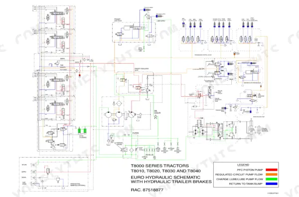
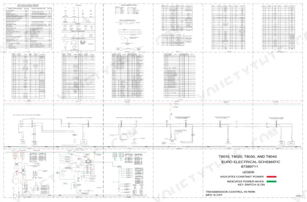
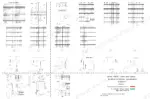
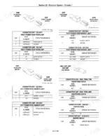
Factory repair manual for the New Holland T8000 series - the T8010, T8020, T8030 and T8040 - running 1751 pages. This is the chassis volume, and it is worth being clear about what that means: engine removal and installation are here, internal engine repair is not, and the book itself directs you to publication 87518858 for the 8.3 and 9.0 litre CNH six-cylinder overhaul. What you get instead is depth everywhere else. The powershift transmission gets its operation, pressure testing and every tractor split. The front axle is treated as several machines rather than one, with standard, suspended and SuperSteer configurations carried separately right down to the fluid capacity tables. Both factory schematic posters are physically bound in rather than sold apart - the hydraulic poster 87518877 at pages 738-739 and the European electrical poster 87389711 at pages 1180-1183, which names all four models on its own face. And the electrical section is not prose: from page 1184 to page 1387 it is socket and pin housing cavity charts, connector locations and circuit references, followed by a chapter of stored fault codes for each of the five controllers on the tractor and the calibration procedures that go with them.
What's Inside This Ford New Holland T8010, T8020, T8030, T8040 Repair Manual
| System | Pages | Key Topics |
|---|---|---|
| General Information: Standard Torques, Capacities and Maintenance Schedule | 1-37 | Standard Torque Specifications, Fluid and Fuel Capacities in US Metric and Imperial Measure, Safety Information, Maintenance Schedule |
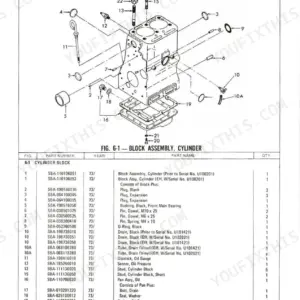
| Engine Removal and Installation | 38-91 | Fuel Tank and Fuel Sender, Hood Removal, Cooling System Module, Viscous Fan Drive Test |
| Powershift Transmission: How It Works, Troubleshooting and Tractor Splits | 92-163 | Powershift Transmission Operation, Pressure Testing, Front Frame to Speed Transmission Split, Speed to Range Transmission Split |
| Speed and Range Transmission Service | 164-331 | Speed Transmission Overhaul, Range Transmission to Rear Frame Split, Range Transmission Overhaul |
| Transmission Control Valves, Rear Frame and Pump Drive | 332-405 | Inching Valve, Hydraulic Pump Drive, Control Valve Overhaul, Rear Frame Service |
| Four-Wheel Drive and Differential Lock Control | 406-475 | FWD Control System Operation, Differential Lock Control System, FWD Output Shaft, FWD Drive Shaft, Suspended FWD Axle Troubleshooting |
| Front Axle Removal and Differentials | 476-547 | Suspended FWD Axle Removal, SuperSteer Axle Removal, Limited Slip FWD Differential, Locking FWD Differential |
| Planetary Hub, Steering Knuckle and Axle Suspension | 548-621 | FWD Planetary Hub, Steering Knuckle, Axle Drive Shaft, Suspension FWD Axle, SuperSteer Vertical Control Linkage |
| Rear Axle and Planetaries | 622-653 | Axle Housing Disassembly, Planetary Assembly Three Pin and Four Pin, Differential Carrier Seal Replacement, How to Determine Ram Pressure, Axle Seal Wear Sleeve for Four-Inch Axle |
| Power Take-Off: Control System and Clutch | 654-717 | PTO Control System Operation, PTO Clutch Assembly, Single Speed Reversible and Dual Speed Variants |
| Brakes: Valve and Cylinders | 718-737 | Brake Valve Service, Brake Cylinder Service, Brake Adjustment |
| Hydraulic Schematic Poster and Symbol Guide | 738-759 | EURO Hydraulic Schematic Poster 87518877, How to Read Hydraulic Symbols, Valve and Pump Symbol Legend |
| Hydraulic System Operation and Remote Valves | 760-833 | Hydraulic System Troubleshooting, PTO and Differential Lock Valve, Remote Valve and Coupler Service |
| Remote Hydraulics, Priority Valve and Pumps | 834-889 | Remote Hydraulic System Operation, Priority and Regulator Valve, Charge Pump, PFC Piston Pump |
| Three-Point Hitch System and Control Valve | 890-951 | Hitch System Operation, Electronic Hitch Control Modes, Hitch Control Valve Overhaul |
| Steering Column, Hand Pump and Wheel Toe-In | 952-973 | Steering Column Removal, Steering Hand Pump, Wheel Toe-In Setting for SuperSteer FWD Axle |
| Air Conditioning: Troubleshooting, Fault Codes and Service | 974-1179 | A/C Fault Codes, Receiver Dryer, Condenser, Compressor, Air Valve and Flush Valve, Special Tools |
| Electrical Schematic Poster, European | 1180-1183 | EURO Electrical Schematic Poster 87389711, Wire Colour Abbreviation Legend, Battery Feed and Clean Ground References, Key Switch Power States |
| Electrical System: Fuses, Connectors and Circuit Diagnostics | 1184-1387 | Cab and Engine Compartment Fuse and Relay Identification, Connector and Component Locations, Socket and Pin Housing Cavity Charts, Power Distribution Circuit Operation, Charging System, Audio System, Exterior Lighting, Symptom Charts |
| Controller Fault Codes: Instrumentation, TMF, Transmission and Armrest | 1388-1647 | Instrumentation Controller Codes, Tractor Multi Function Controller Codes, Transmission Controller Codes, Suspended Axle Codes, Armrest Controller Codes |
| Controller Configuration, Calibration and Fault Code Retrieval | 1648-1723 | Fault Code Retrieval Procedure, Instrumentation Programming, Radar Calibration, Clutch Calibration, Calibration Error Messages, Front Suspension Calibration, Remote and Hitch and PTO Calibration |
| Cab, Hood and Seat | 1724-1751 | Pedal and Pedal Switch Adjustments, Cab Raise, Cab Removal and Installation |
Quick Reference Specifications
| Specification | Value | Page |
|---|---|---|
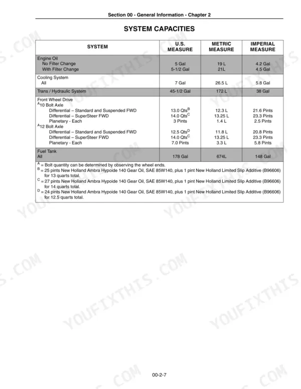
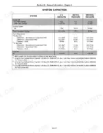
| Engine oil capacity, with filter change | 5-1/2 Gal (21 L) | p. 36 |
| Cooling system capacity | 7 Gal (26.5 L) | p. 36 |
| Transmission / hydraulic system capacity | 45-1/2 Gal (172 L) | p. 36 |
| Fuel tank capacity | 178 Gal (674 L) | p. 36 |
| Front wheel drive differential capacity | 13.0 Qts (12.3 L) / 14.0 Qts (13.25 L) / 12.5 Qts (11.8 L) | p. 36 |
| Front wheel drive planetary capacity, each | 3 Pints (1.4 L) / 7.0 Pints (3.3 L) | p. 36 |
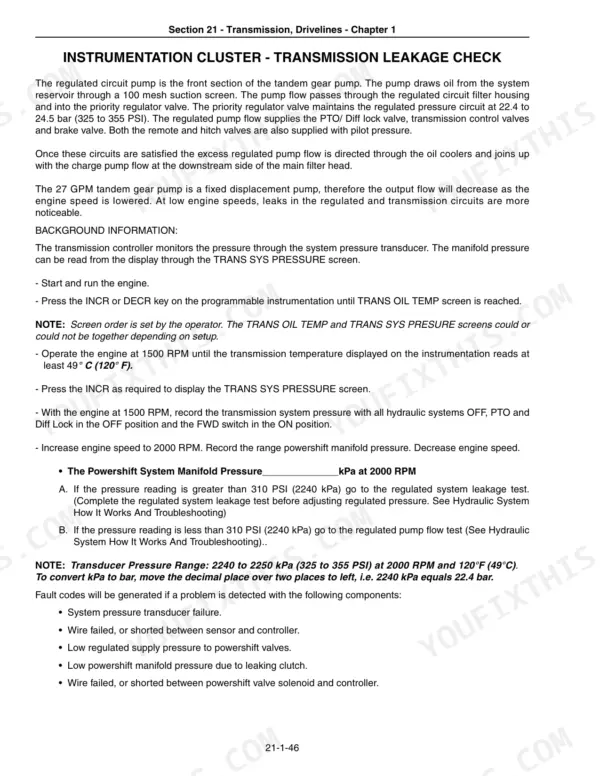
| Regulated pump flow | 27 GPM | p. 137 |
| Regulated system pressure | 2240 to 2250 kPa (325 to 355 PSI), measured at 2000 RPM and 120 F (49 C) | p. 137 |
| Three point hitch category | Category III/IIIN | p. 892 |
| Slip limit control mode activation speed | above 2 mph | p. 895 |
| Load control mode activation speed | 0.5 mph or faster | p. 898 |
| Front wheel drive automatic disengage speed | exceeds 10 MPH | p. 902 |
| Front wheel drive re-engage speed | drops below 8 MPH | p. 902 |
| PFC piston pump fill on installation | 2 Liters (2.1 U.S. Quarts) of hydraulic fluid | p. 889 |
| Pilot relief valve assembly torque | 75 to 108 Nm (55 to 80 lb. ft.) | p. 870 |
| Regulator spool lock nut torque | 41 to 48 Nm (30 to 35 lb. ft.) | p. 870 |
| Rear wheel axle bushing bolts torque | 300 to 350 Nm (220 to 260 lb. ft.) | p. 885 |
| Hitch valve mounting bolts, M12 | 40 to 45 Nm (30 to 33 lb. ft.) | p. 920 |
Ford New Holland T8010, T8020, T8030, T8040 Common Problems This Manual Covers
A fault appears on the display but the code cannot be found in any list you have.
The T8000 stores codes in five separate controllers, and the code means nothing until you know which one reported it. Use the retrieval procedure at page 1648 to step through the controllers on the display, then take the code to that controller's own chapter. Each holds up to ten codes, so an intermittent fault from weeks ago may still be sitting there.
Transmission feels sluggish or slips and there is no obvious mechanical damage.
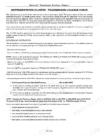
Test the regulated system before opening anything. The book specifies 2240 to 2250 kPa (325 to 355 PSI) at 2000 RPM with oil at 120 F, and regulated pump flow of 27 GPM, both on page 137. The temperature and engine speed are part of the specification, not advice - a reading taken cold will mislead you.
Chasing an electrical fault with no way to identify the connector you are holding.
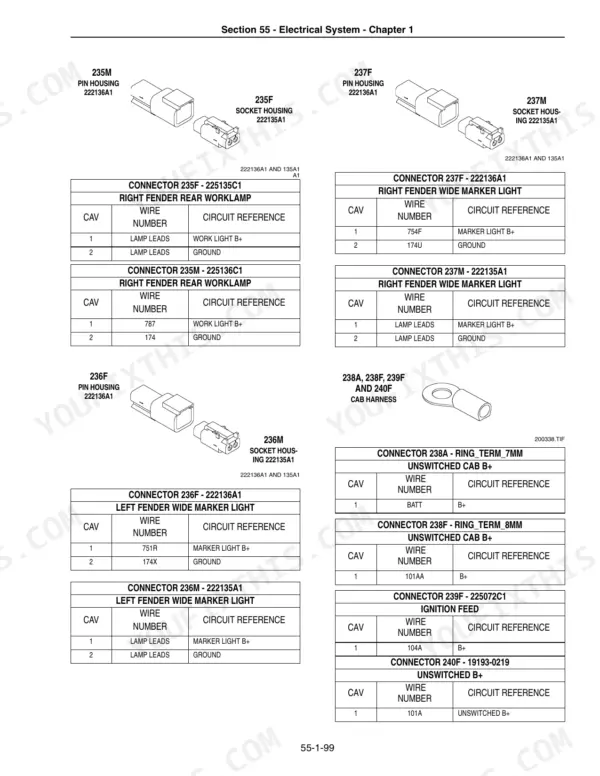
Pages 1184 to 1387 are largely connector documentation: socket and pin housing cavity charts with circuit references, plus connector and component location drawings and the cab and engine compartment fuse and relay identification. Find the connector, read the cavity chart, then follow the circuit onto the bound-in schematic poster at pages 1180 to 1183.
Rear axle planetary rebuilt to the wrong specification.
The rear axle comes in more than one build. The manual carries separate planetary assembly procedures for three pin and four pin carriers, and a wear sleeve installation that applies to the four-inch axle only. Identify which you have before ordering parts - the procedures are on pages 622 to 653.
Frequently Asked Questions
Does this manual cover rebuilding the engine?
No, and the book says so itself. Section 10 is engine removal and installation only - getting the engine out of the tractor and back in. For internal repair of the 8.3 and 9.0 litre CNH six-cylinder, New Holland publishes a separate engine manual, number 87518858. Everything else on the tractor is here.
Are the wiring and hydraulic schematics actually included, or referenced?
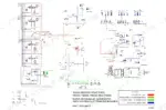
Included. Both factory posters are physically bound into this volume as oversized fold-out sheets: the EURO HYDRAULIC SCHEMATIC 87518877 on pages 738-739, and the EURO ELECTRICAL SCHEMATIC 87389711 on pages 1180-1183. The electrical poster carries the full wire colour legend and names all four models on its face. p. 738
How do I find a fault code on a T8000?
There is no single code list, because the tractor has five separate controllers and each stores its own codes. The book gives you a chapter per controller - instrumentation, Tractor Multi Function for aux, hitch and PTO, transmission including suspended axle, and armrest - plus a retrieval procedure at page 1648 that walks you through selecting a controller on the display. Each controller stores up to ten codes. p. 1648
Does it cover the SuperSteer front axle?
Yes, as a distinct configuration rather than a footnote. SuperSteer axle removal and installation, the vertical control linkage, and the SuperSteer wheel toe-in setting each have their own coverage, and the fluid capacity tables list SuperSteer separately from the standard and suspended axles on both the 10 bolt and 12 bolt axles. p. 36
Is this the operator's manual?
No. This is the repair manual - the service book a technician works from. It refers to the operator's manual for daily operating and routine capacity information, but does not reproduce it.



Reviews
There are no reviews yet.