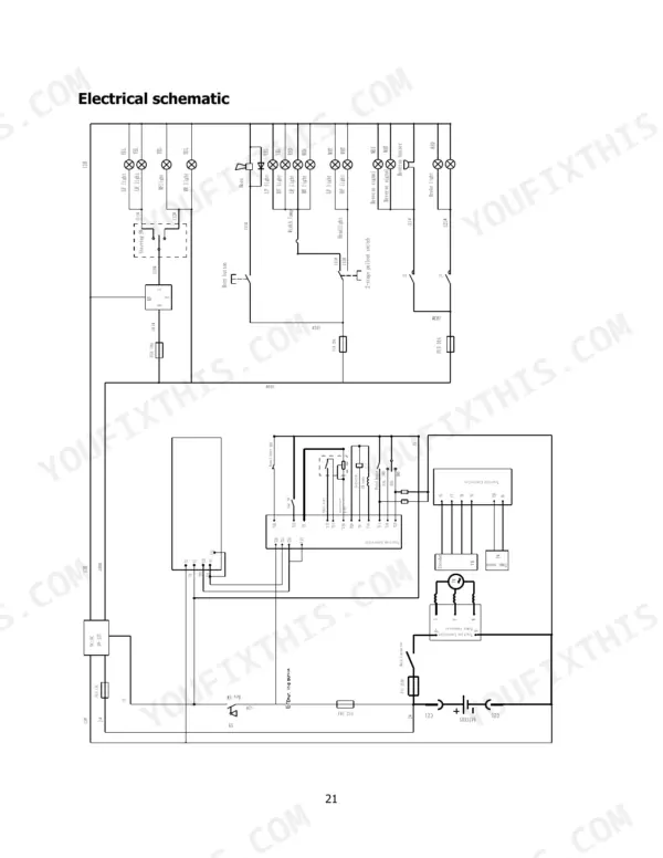
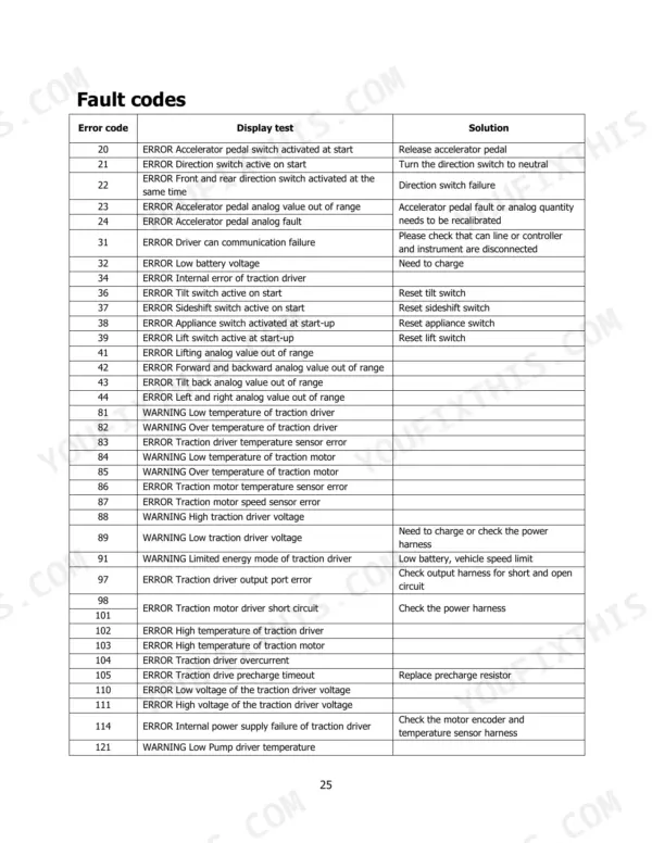
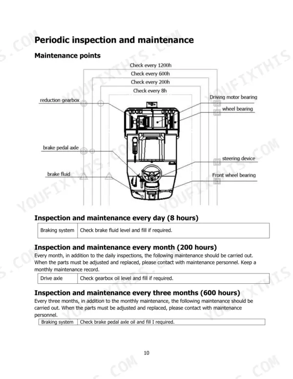
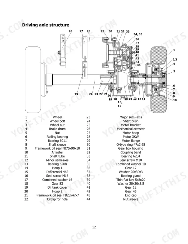
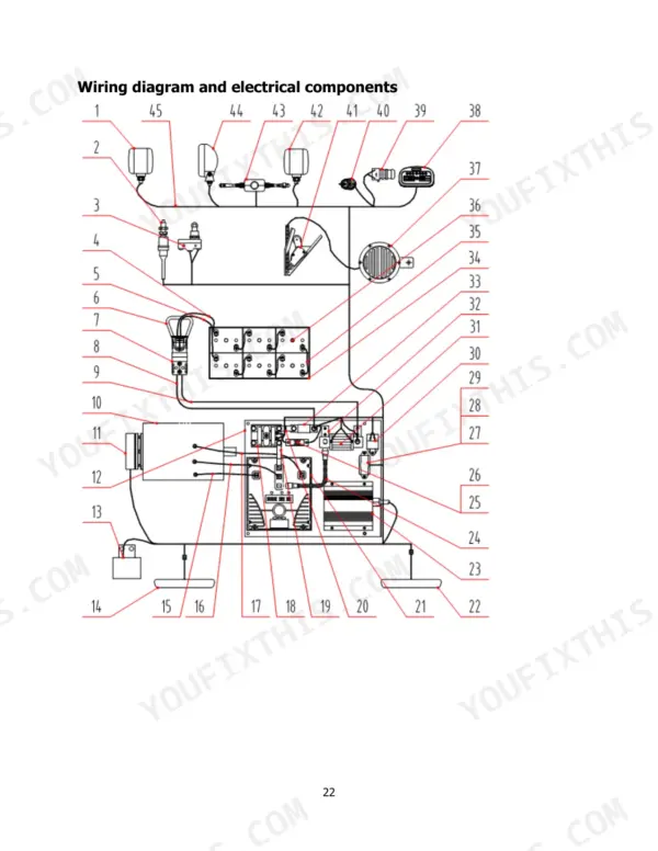
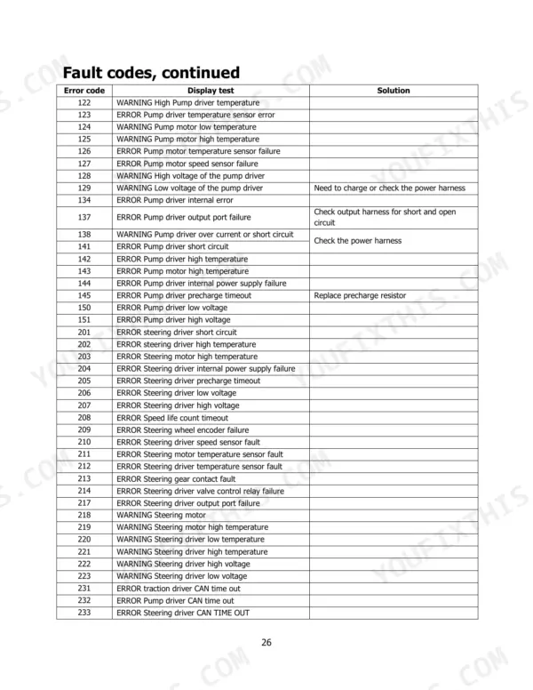
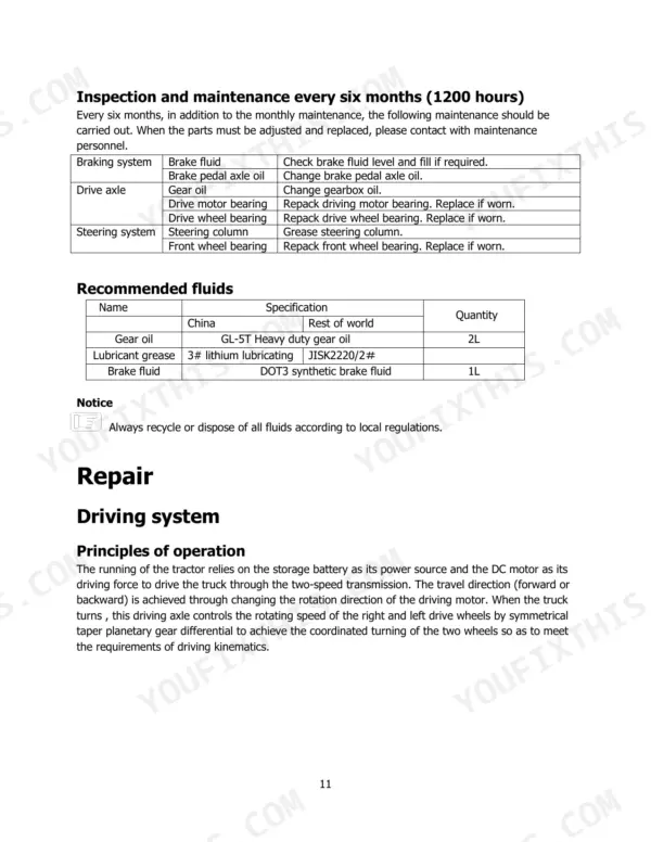
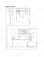
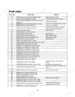
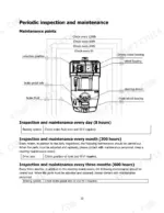
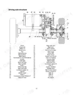
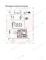
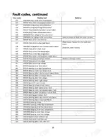
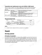
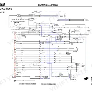
Hyster's own factory publication 4279936 is the source of this 28-page Hyster T3.0UT service manual PDF, written for the T3.0UT sit-drive electric tow tractor. Its electrical schematic and wiring diagram show how the circuits and components connect, and fault code tables let you match a displayed code to its cause, backed by a mechanical breakdowns chart. Repair chapters explain the drive axle, wheel hub, steering and both brakes, while the maintenance schedule runs from daily (8 hours) through 200, 600 and 1200 hour checks. Charging figures are exact. A new truck's initial charge runs 30A in the first stage and 15A in the second, with 28.8V listed as the charge voltage. When you check the park brake during brake maintenance, the figure it must meet is a hold on a 6% slope. Bookmarks open onto the axle and wheel hub structure views, so you confirm which drive component you are replacing before ordering.
What's Inside This Manual
| System | Pages | Key Topics |
|---|
| Description of Symbols | 4 | Danger, Warning, Caution |
| Maintenance | 5 | Precautions During Maintenance (Places for Maintenance, Precautions Before Repair and Maintenance) |
| Setting Up a New Truck | 6 | Initial Charge |
| Battery Use and Maintenance | 7-8 | Common Charge, Balancing Charge, Equalizing Charge, Battery Storage, Maintenance of Electrolyte, Operation of Storage Batteries During the Final Stage of Their Lifetime |
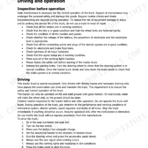
| Daily Inspection | 9 | Electric System, Battery, Brake System |
| Periodic Inspection and Maintenance | 10 | Maintenance Points, Recommended Fluids |
| Recommended Fluids | 11 | Inspection and Maintenance Every Six Months (1200 Hours), Principles of Operation |
| Driving System | 11-15 | Inspection and Maintenance Every Six Months (1200 Hours), Principles of Operation, Driving Axle Structure, Wheel Hub Structure |
| Steering System | 16-17 | Principles of Operation, Steering System Structure, Steer Wheel Structure, Steer Wheel Description |
| Brake System | 18-19 | Principles of Operation, Service Brake System Structure, Service Brake Description, Park Brake Description |
| Electrical System | 20-23 | Principles of Operation, Electrical Schematic, Wiring Diagram and Electrical Components |
| Troubleshooting | 24-26 | Mechanical Breakdowns, Fault Codes (Fault Codes, Continued) |
| Truck Storage and Transportation | 27-28 | Loading and Unloading, Transportation of Truck, Storing the Truck |
Quick Reference Specifications
| Specification | Value | Page |
|---|
| Initial charge current (first stage) | 30A | p. 6 |
| Initial charge current (second stage) | 15A | p. 6 |
| Charger output voltage | 24V | p. 9 |
| Charger output current | 20-30A | p. 9 |
| Park brake slope hold | 6% | p. 19 |
| Initial charge voltage (switch to second stage) | 28.8V | p. 6 |
| Second stage charge current | 15A | p. 6 |
| Gear oil capacity | 2L | p. 11 |
| Brake fluid capacity | 1L | p. 11 |
| Equalizing charge current (initial) | 4A | p. 8 |
| Equalizing charge current (reduced) | 2A | p. 8 |
| Park brake slope hold requirement | 6% | p. 19 |