



This Kubota Workshop Manual covers the L4600 utility tractor, built around the V2203-M-E3-LB3 diesel engine. It is the full factory service manual, publication number 9Y111-07611, 403 pages with a searchable text layer and bookmarks.
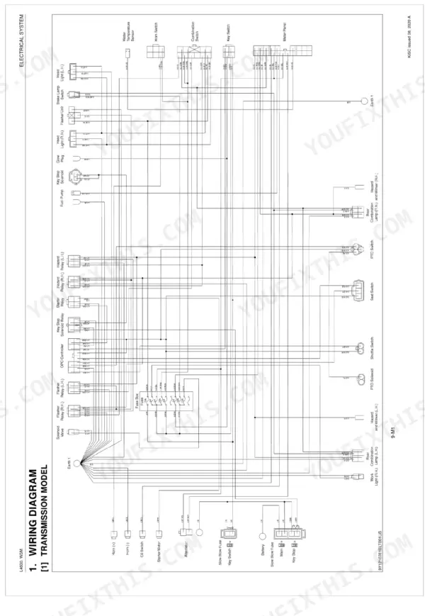
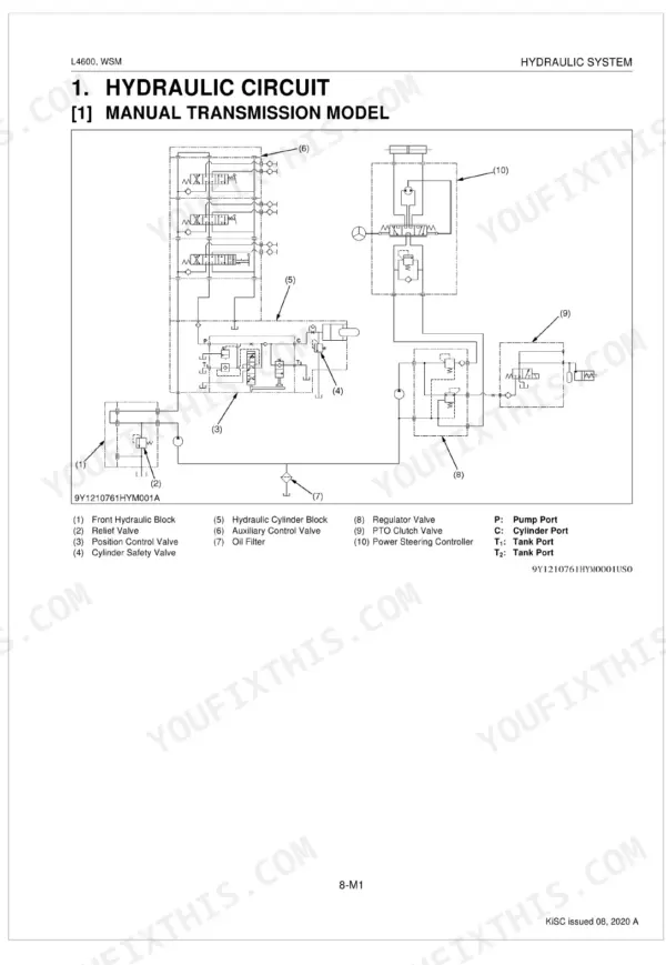
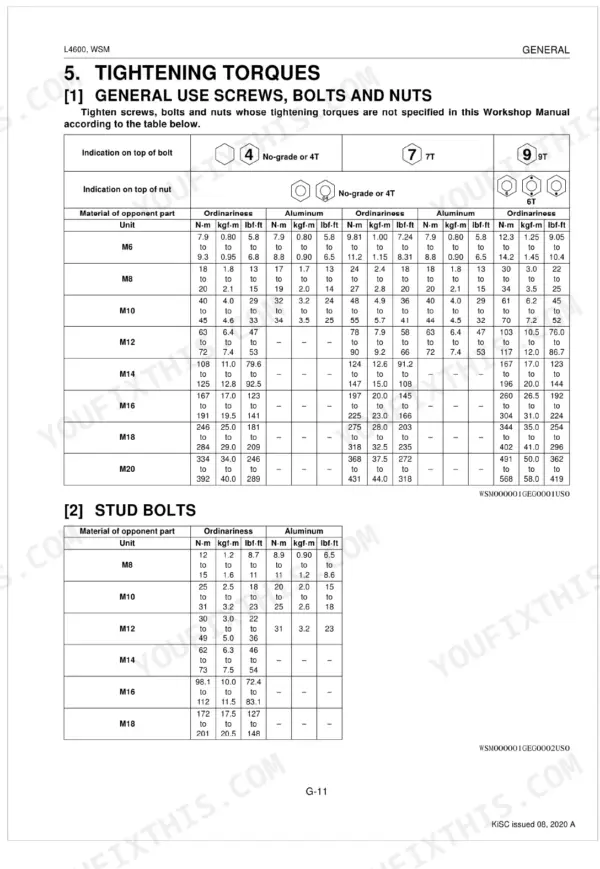
Coverage runs the length of the machine: Engine, Clutch, Transmission in both manual and HST forms, Rear Axle, Brakes, Front Axle, Steering, Hydraulic System, and the Electrical System with wiring diagrams. Every section includes servicing specifications, tightening torques, and detailed checking, disassembly, and assembly steps.
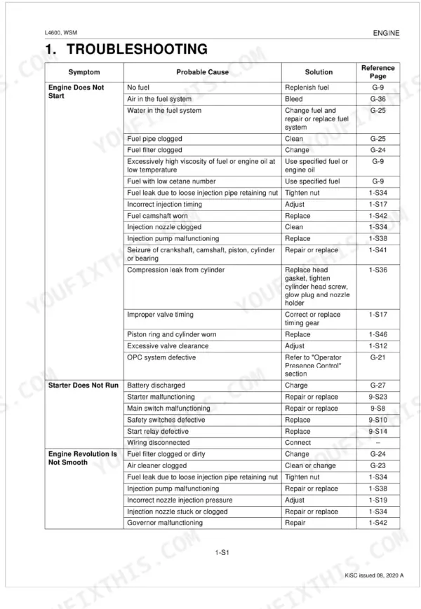
Use it to trace an intermittent no-start through the wiring and switches, set valve clearance and fan belt tension, rebuild the clutch, service the three point hydraulics, and torque wheels and head bolts correctly. This is dealer level documentation delivered as a downloadable PDF you can search on a computer, print, or carry on a tablet in the shop.
What's Inside This Kubota L4600 Manual
| System | Pages | Key Topics |
|---|---|---|
| Information | 4-14 | |
| General | 15-73 | Tractor Identification, Model Name and Serial Numbers, E3 Engine, Cylinder Number, General Precautions, Handling Precautions for Electrical Parts, Wiring, Battery |
| Engine | 74-144 | Preparation |
| Clutch | 145-165 | Traveling Clutch, HST Model, Preparation |
| Transmission | 166-261 | Manual Transmission Model (4WD), HST Model (4WD), Manual Transmission Model, Power Train for Travelling Gear, HST Model, Power Train, PTO System, HST |
| Rear Axle | 262-271 | Preparation, Disassembling Rear Axle |
| Brakes | 272-285 | Operation, Preparation |
| Front Axle | 286-305 | 4WD Type, Front Wheel Alignment, Preparation |
| Steering | 306-326 | Linkage, Hydraulic Circuit, Hydraulic Pump, Steering Controller, Control Valve, Metering Device (Gerotor), Steering Cylinder |
| Hydraulic System | 327-364 | Hydraulic Circuit, Manual Transmission Model, HST Model, Position Control Valve, Mechanical Transmission, Hydraulic Cylinder, Linkage Mechanism, Position Control |
| Electrical System | 365-403 | Wiring Diagram, Transmission Model, HST Model, Operator Presence Control, Electric Circuit, Seat Switch and Opc Timer |
Every system also includes tightening torques, disassembling and servicing, and troubleshooting.
Documents This Manual Refers To
The manufacturer cites these publications by number. We carry them:
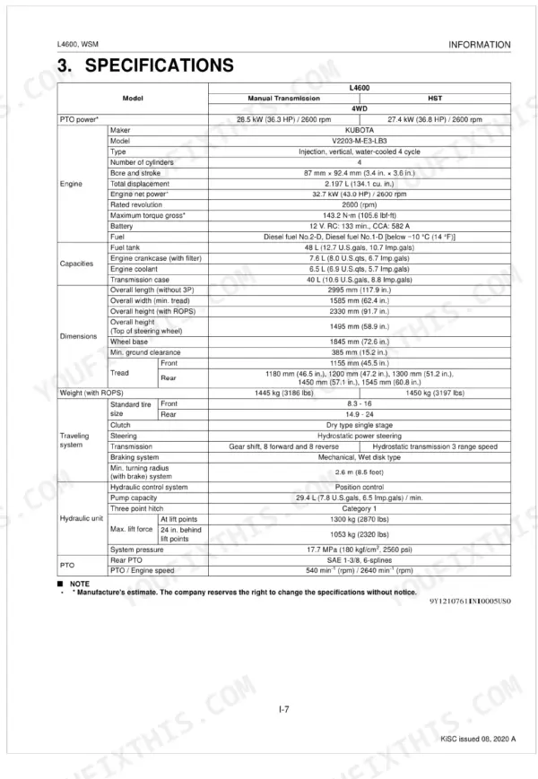
Quick Reference Specifications
| Specification | Value | Page |
|---|---|---|
| Front wheel mounting nut | 137 N-m (14.0 kgf-m, 100 lbf-ft) | p. 293 |
| Rear wheel mounting screw and nut | 215 N-m (22.0 kgf-m, 160 lbf-ft) | p. 195 |
| Cylinder head screws | 93.1 to 98.0 N-m (9.5 to 10.0 kgf-m, 68.7 to 72.3 lbf-ft) | p. 88 |
| Battery Type | 80D26R | p. 43 |
| Volts (V) | 12 | p. 43 |
| Glow Relay (Key Stop Solenoid Relay) Resistance Terminal 1 - Terminal 3 | 0 Ω | p. 389 |
| Glow Relay (Key Stop Solenoid Relay) Resistance 1 to 4: Terminal | 0 Ω | p. 389 |
| Main Switch Key at OFF Position Resistance B terminal - AC terminal | Infinity | p. 383 |
| Main Switch Key at OFF Position Resistance B terminal - ST terminal | Infinity | p. 383 |
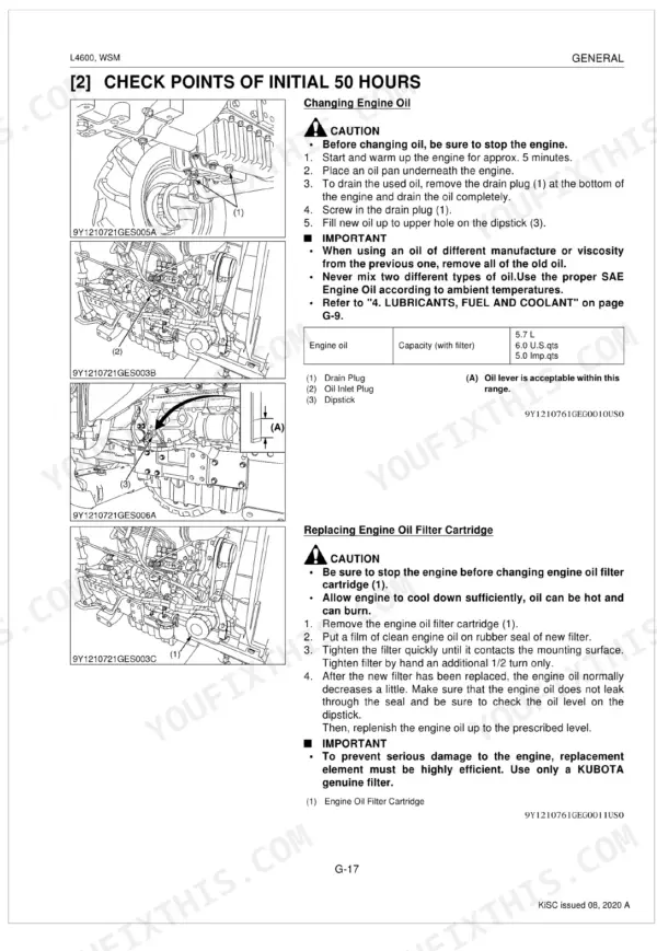
| Fuel filter element replacement interval | 400 Hr | p. 30 |
| Transmission oil filter [HST model] replacement interval | 200 Hr | p. 30 |
| Radiator hose and clamp replacement interval | 2 years | p. 30 |
