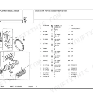
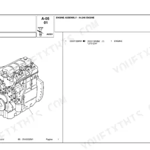
Covers the Landini Powerfarm 60, 65, 75, 85, 95 and 105, plus the Powerfarm and Powershuttle 75, 85, 95 and 105. Engines are the Perkins 1103C-33, 1104C-44 and turbo 1104C-44T. The book is Landini's training manual 3675939M2, Pre-Sale Service edition, November 2005, and its 1119 pages carry full service content.
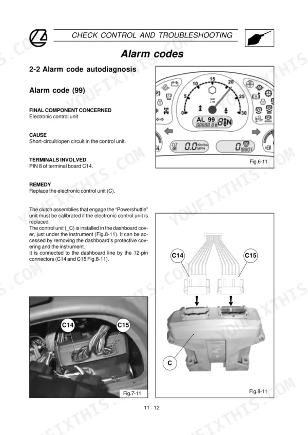
You get Speedfour and Powershuttle power train diagrams, driving torques, hydraulic circuit and wiring diagrams, power lift tests and adjustments, clutch calibration and the alarm code list. Every day the tractor sits with a shuttle alarm on the dash is a day of drilling or baling lost to the weather.
Order against number 3675939M2 so the book on your bench is the one written for the tractors in your shed.
What's Inside This Manual
| System | Pages | Key Topics |
|---|---|---|
| Introduction | 5-80 | Tractor Identification, Weights and Dimensions, Engine/Clutch/PTO/Axle/Hydraulic Specifications, Safety Decals, Periodical Maintenance Table, Conversion Units |
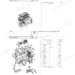
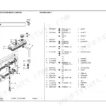
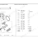
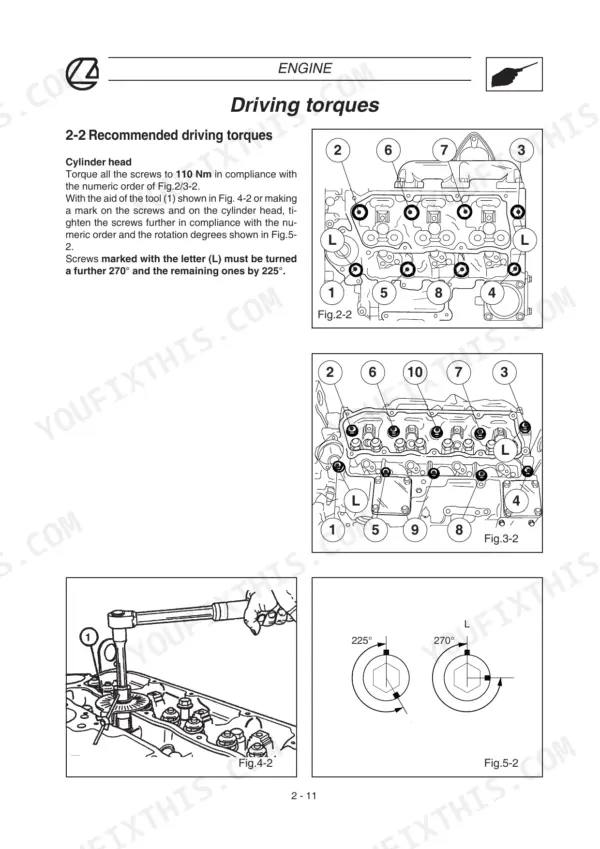
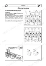
| Engine | 81-98 | Perkins Main Technical Specifications, Recommended Driving Torques, Cylinder Head Tightening Sequence, Finding Compression TDC |
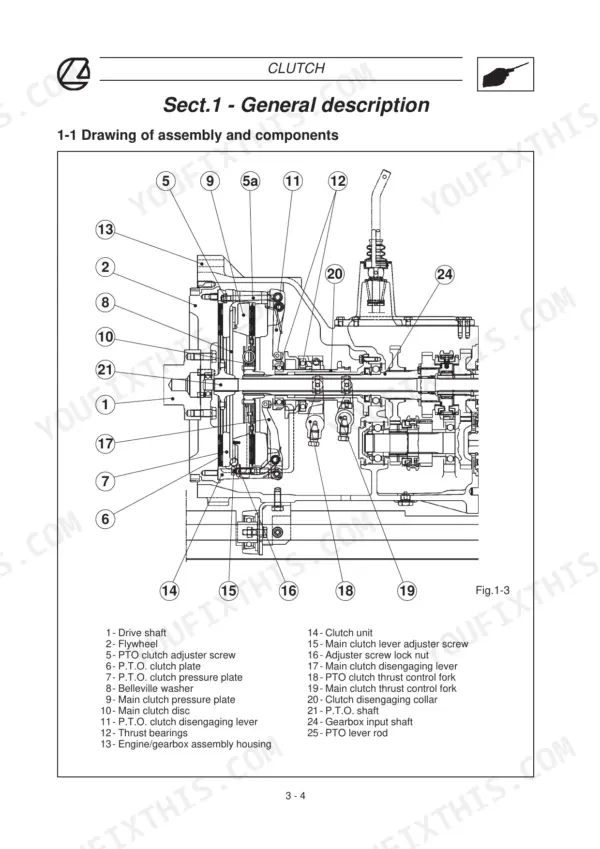
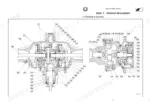
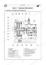
| Clutch | 99-114 | Assembly Drawing, Valve System Components, Specifications, Inspection and Overhaul, Adjustment |
| Transmission | 115-255 | Speedfour and Powershuttle Assemblies, Control Devices, Power Train Diagrams, Specifications, Driving Torques and Sealants |
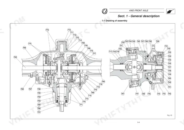
| 4WD Front Axle | 256-291 | Spring-On 4WD Engagement, Front Brakes, Specifications, Driving Torques, Disassembly and Re-Assembly |
| Power Take-Off | 292-333 | Assembly, Controls, Specifications, Driving Torques, Disassembly and Re-Assembly Guidelines |
| Hydraulic Circuit | 334-509 | Hydraulic Pump, Trailer Brake, Auxiliary Control Valves, Hydraulic Braking System, Brake Bleeding and Adjustment, Operating Pressure Tests, Circuit Diagrams |
| Mechanical Power Lift | 510-567 | Standard and Load Sensing Valve Systems, Specifications, Hydraulic Tests, Adjustments, Troubleshooting |
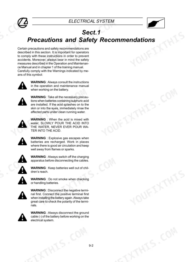
| Electrical System | 568-979 | Electricity Symbols, How to Read a Wiring Diagram, Cable Colour Chart, Wiring and Connector Locations, Wiring Diagrams |
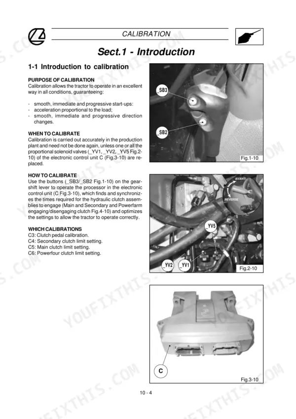
| Calibration | 980-1003 | Components Involved, When to Calibrate, Clutch Calibration Procedure |
| Troubleshooting | 1004-1043 | Check-Control, Conventional Troubleshooting, Alarm Code Autodiagnosis |
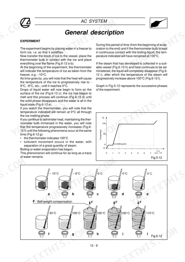
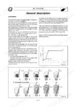
| Air Conditioning System | 1044-1083 | Operating Principle, Main Components, Specifications, Maintenance, Recharging Procedure, Efficiency Check |
| Special Tools | 1084-1119 | Special Tool List |
Quick Reference Specifications
| Specification | Value | Page |
|---|---|---|
| Engine codes (Perkins) | 1103C-33 (Mod. 60), 1104C-44 (Mod. 75, 85), 1104C-44T (Mod. 95, 105) | p. 14 |
| Bore x stroke | 105 mm x 127 mm | p. 14 |
| Rated engine speed / idling speed | 2200 rpm / 750 rpm | p. 14 |
| Tappet gap, cold engine, intake / exhaust | 0.20 mm / 0.45 mm | p. 14 |
| Max. torque | 222 Nm (Mod. 60) to 380 Nm (Mod. 95) at 1400 rpm | p. 14 |
| Cylinder head screws | 110 Nm in numeric order, then a further 270 degrees (screws marked L) or 225 degrees (the rest) | p. 91 |
| Main bearing retention screws (5/8 UNF) | 245 Nm | p. 92 |
| Drive shaft pulley retention screw (7/16 UNF) | 115 Nm | p. 92 |
| Hydraulic pump maximum operating pressure (Speedfour version) | 180 bar | p. 30 |
| Steering calibration valve, 2WD / 4WD axles | 125 ± 5 bar / 150 ± 5 bar | p. 30 |
| Auxiliary control valves and power lift calibration valve | 180 ± 5 bar | p. 31 |
| PTO 540 rpm | engine at 1944 rpm | p. 25 |