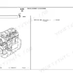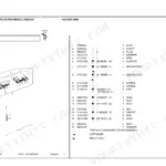
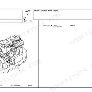
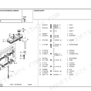
Fits the Landini Vision 80, Vision 90 and Vision 100 in Speedfive, Powerfive and Powershuttle form, footstep or cab. The Vision 80 runs the Perkins 1004.42, the 90 and 100 the turbo 1004.40T, and both engines are covered.
The book runs from the front axle back to the rear PTO. It covers the clutch, gearbox, rear differential, final drives, brakes, mechanical and electronic power lift, front linkage and front PTO, hydraulic pressure tests and air conditioning. There are four separate wiring diagram sets, one for each transmission and platform combination.
A tractor parked mid-season with a slipping shuttle loses you every dry day it sits in the shed. Keep this on a phone or tablet in the cab, so the hydraulic specs are right there next to the pressure gauge.
What's Inside This Manual
| System | Pages | Key Topics |
|---|---|---|
| Introduction, Identification & Maintenance | 1-57 | Tractor Identification, Weights and Dimensions, Safety Decals, Pre-Delivery Inspections, Routine Maintenance Table, Unit Conversion Tables, Loctite Sealants, Standard Driving Torques, Seals and Bearings |
| Engine (Perkins 1004.42 / 1004.40T) | 58-77 | Main Technical Specifications, Standard and Recommended Driving Torques, Compression TDC of Cylinder No. 1, Camshaft Timing Check, Injection Pump Timing Check |
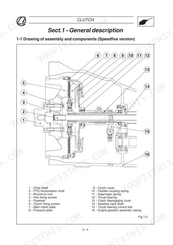
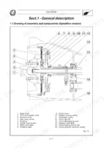
| Clutch | 78-91 | Speedfive Clutch Assembly and Operation, Powerfive/Powershuttle Damper, Technical Specifications, Inspections and Overhauls |
| Transmission: Description & Specifications | 92-123 | Speedfive, Powerfive and Powershuttle Layouts, Control Levers, Power Train Diagrams, Technical Specifications, Driving Torques and Sealants |
| Transmission: Engine-Gearbox Assembly Overhaul | 124-175 | Engine-Gearbox Assembly for Speedfive, Powershuttle and Powerfive/Powershuttle Versions |
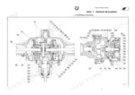
| Gearbox, 4WD Housing, Rear Differential, Final Drives & Rear Brakes | 176-235 | Gearbox, 4WD Housing, Bevel Gear Pair and Rear Differential, Side Final Drives, Rear Brakes |
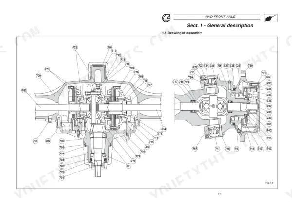
| 4WD Front Axle | 236-271 | Assembly and Main Components, 4WD Clutch (Spring-On), Front Brakes, Technical Specifications, Driving Torques, Disassembly and Re-Assembly, Inspections and Adjustments |
| Rear Power Take-Off | 272-299 | Independent and Proportional PTO, Controls, Power Train Diagrams, Specifications, Disassembly, Re-Assembly and Adjustments |
| Hydraulic Circuit: General Circuits & Specifications | 300-346 | General Hydraulic Circuit for Speedfive, Powershuttle and Powerfive Versions, Pump, Steering and Power Pack Specifications |
| Hydraulic Braking System | 347-357 | Hydraulic Braking Circuit, Brake Pump with Compensator, Bleeding Front and Rear Brake Circuits, Brake Adjustment, Brake Circuit On-Off Valve |
| Hydraulic Circuit: Components & Pressure Tests | 358-491 | Hydraulic Pump, Power Steering, Forced Lubrication Valve Block, Hydraulic Clutches, Diff Lock, PTO and 4WD Oil Supply, Trailer Brake, Auxiliary Control Valves, Low and High Pressure Circuit Tests |
| Mechanical Power Lift | 492-529 | Operating Modes, Valve System Components and Phases, Specifications, Power Lift Adjustments, Operating Pressure Checks, Troubleshooting |
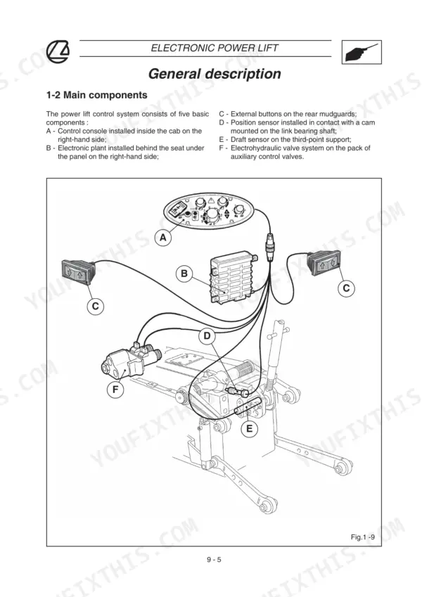
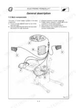
| Electronic Power Lift | 530-585 | Hydraulic Circuit and Valve Block, Wiring Diagram and Connectors, Quick Operating Test, Fault Code Tables, Operating Pressure Tests |
| Front Power Lift & Front PTO | 586-633 | Front PTO, Front Power Lift, Specifications, Disassembly and Adjustments, Hydraulic Circuit, Special Tools |
| Electrical System: General & Cable Colour Chart | 634-662 | Basic Concepts, Electricity Symbols, Reading a Functional Wiring Diagram, Cable Colour Chart, Wiring Locations, Battery-Starter Motor Line |
| Wiring Diagrams: Speedfive Footstep Version | 663-721 | Battery and Alternator Specifications, Component Identification, Main Wiring Diagram, Wiring Lines and Connectors |
| Wiring Diagrams: Speedfive Cab Version | 722-797 | Technical Specifications, Connection Points, Wiring Lines and Connectors |
| Wiring Diagrams: Powershuttle Footstep Version | 798-871 | Connector (C25) for Electronic Control Unit, Platform Line, Line for Controls on RH Side, Connector (H6) for the Diff Lock Button, Safety Connection (H8), Roof Line (Rollbar) |
| Wiring Diagrams: Powershuttle Cab Version | 872-955 | Technical Specifications, Connection Points, Wiring Lines and Connectors |
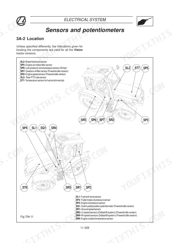
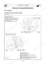
| Electrical Main Components | 956-1013 | Sensors and Potentiometers, Solenoid Valves, Switches and Buttons, Instrument, Reverse Shuttle Lever, Powershuttle Electronic Control Unit |
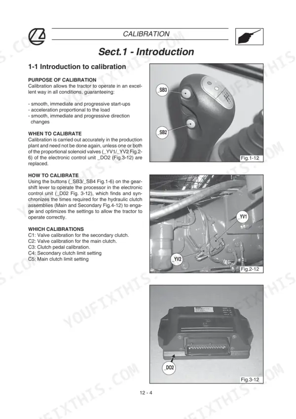
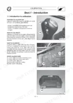
| Calibration, Check-Control & Alarm Codes | 1014-1073 | Powershuttle Calibration Procedure and Conditions, Conventional Troubleshooting, Alarm Code Check-Control |
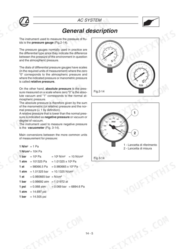
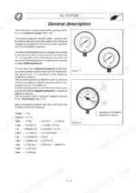
| Air Conditioning System & Special Tools | 1074-1157 | AC Operating Principle and Components, AC Wiring Diagram, Emptying and Recharging, System Efficiency Test, Special Tools |
Quick Reference Specifications
| Specification | Value | Page |
|---|---|---|
| Engine type | Perkins 1004.42 (Vision 80); Perkins 1004.40T (Vision 90, Vision 100) | p. 63 |
| Swept volume | 4.233 liters (Vision 80); 3.99 liters (Vision 90/100) | p. 63 |
| Power rating DIN 70020 | 57 kW / 78 HP (Vision 80); 65 kW / 88 HP (Vision 90); 68 kW / 93 HP (Vision 100) | p. 63 |
| Max torque DIN 70020 | 284 Nm at 1400 RPM (Vision 80); 358 Nm at 1400 RPM (Vision 90); 368 Nm at 1400 RPM (Vision 100) | p. 63 |
| Injection pump type | DP202 | p. 63 |
| Valve clearance (cold) | Intake 0.20 mm; exhaust 0.45 mm | p. 64 |
| Hydraulic pump maximum operating pressure | 180 bar | p. 343 |
| Hydraulic pump maximum flow rate (at 2200 RPM) | 53.9 l/min | p. 343 |
| Quantity of hydraulic oil / transmission | 35 l | p. 343 |
| Steering calibrating valve | 150±5 bar | p. 343 |
| Steering antishock valve setting | 200 bar | p. 343 |
| Hydraulic power pack low pressure calibrating valve | 20 bar | p. 343 |