


Part of the New Holland Repair Manuals.
When the hydrostatic drive on your L-555 starts creeping in neutral, the New Holland L-555 service manual PDF (OEM 40055510), the factory book covering the L-550 Series, puts the fix on the bench: 116 factory pages that take the tandem piston pumps, drive motors, and chain-case final drive down to parts and build them back to spec. Hydraulic schematics map the charge circuit, loader valve, and relief plumbing, while wiring diagrams trace the starter circuit and the seat-activated boom lockout that keeps killing your lift circuit. A dedicated troubleshooting section walks service problem evaluation before you spend money on parts. Bench-test the gear pump against its rated 14 GPM at 2800 RPM, and verify boom relief at 2750 psi before you condemn a slow cylinder. Nobody answers the phone when the loader quits at 6 a.m., but this book does. Print the pages you need and let them get greasy; the bookmarked, keyword-searchable file stays clean.
What's Inside This New Holland L-555 Manual
| System | Pages | Key Topics |
|---|---|---|
| Introduction | 2-3 | Service Manual, Operator's Manual, Engine Repair, Safety Instructions, Parts Ordering |
| Safety | 4-6 | Personal Safety |
| Operation | 7-10 | Hydrostatic Drive, Tandem Pump Configuration, Variable Displacement Piston Pumps, Gear Pump, Steering Control Levers, Neutralizers |
| Steering Adjustments | 11-12 | Drive Control Adjustment, Neutralizer, Neutralizer Tube Assembly, Creep Adjustment, Control Arm Yokes, Control Arm Stop Bolts |
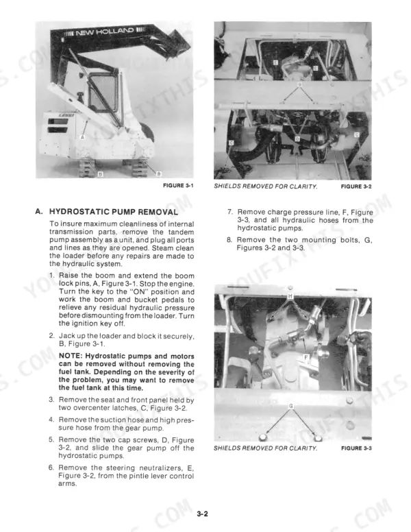
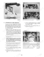
| Hydrostatic Transmission Removal | 13-18 | Hydrostatic Pump Removal, Hydrostatic Motor Removal |
| Hydrostatic Pump Overhaul | 19-30 | Disassembly, Inspection of Parts, System Cleaning Procedure |
| Hydrostatic Transmission Motors | 31-46 | Disassembly, Parts Inspection, Reassembly of Hydrostatic Motor |
| Gear Pump | 47-52 | Gear Pump Removal, Gear Pump Disassembly, Parts Inspection |
| Boom and Bucket Cylinders | 53-56 | Cylinder Removal, Inspection |
| Control Valve | 57-64 | Servicing the Control Valve, Control Valve Removal, Spools and O-Rings |
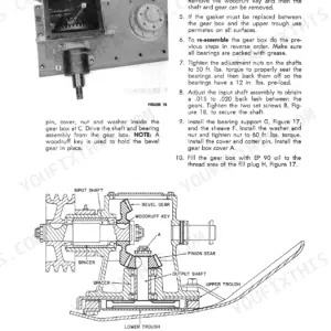
| Final Drive | 65-84 | Chain and Gear-Sprocket Drive Disassembly, Front Axle Disassembly, Final Drive Reassembly |
| Electrical System | 85-94 | Starter Removal and Replacement |
| Seat Activated Boom Lockout | 95-98 | Boom Lift Circuit, Electronic Solenoid, Seat Switch, Interlock Operation |
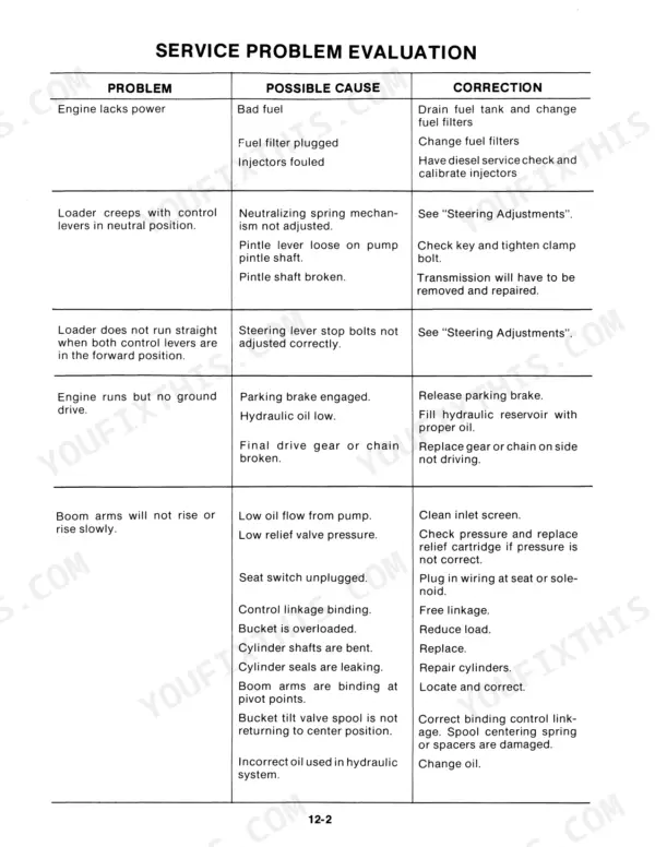
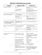
| Troubleshooting | 99-102 | Service Problem Evaluation |
| Specifications | 103-112 | Engine, Electrical System, Hydrostatic Transmissions, Hydraulic System, Cylinders, Travel Speeds |
Quick Reference Specifications
| Specification | Value | Page |
|---|---|---|
| Gear pump capacity | 14 GPM (52.9 LPM) at 2800 RPM | p. 47 |
| Master relief valve pressure | 1,875 psi (129 bar) | p. 9 |
| Charge line filter bypass pressure | 150 psi (10.35 bar) | p. 9 |
| Boom relief valve pressure | 2750 psi (190 bar) | p. 9 |
| Pump housings to valve plate bolts | 27-31 ft. lbs. (37-42 N·m) | p. 28 |
| Hydrostatic pump coupler bolts | 55-60 ft. lbs. (74-81 N·m) | p. 28 |
| Drive shaft rolling torque after assembly | 5 ft. lbs. (7 N·m) maximum | p. 31 |
| Main system relief valve factory setting | 1,875 psi (129 bar) | p. 58 |
| System pressure range at 120°F (49°C) | 2,050-2,400 psi (141-166 bar) | p. 58 |
| Main system relief pressure | 2000 to 2300 psi | p. 104 |
| Transmission Relief Valve Pressure | 3000 psi | p. 9 |
| Hydrostatic Pump to Engine Bolt Torque | 40-45 ft. lbs. | p. 13 |
New Holland L-555 Common Problems This Manual Covers
New Holland L-555 hydraulics weak after warm-up, lift arms slow and pump whines loudly
Check main system pressure with the oil at 120°F (49°C); healthy readings run 2,050-2,400 psi per the control valve data on page 58. If pressure stays low with the relief set at 1,875 psi, test gear pump output against its 14 GPM at 2800 RPM rating on page 47, then replace the pump or clean the suction strainer.
Manual Section: Control Valve p. 58One drive side weak or slipping, only pulls at certain lever positions
Test charge pressure on the weak side first; it must hold 150-190 psi per the overhaul procedure on page 29. If charge checks good, verify the forward and reverse relief valves at 3,000 psi. Persistent slip means internal pump or motor wear, so pull the hydrostatic unit following the removal steps starting on page 13.
Manual Section: Hydrostatic Pump Overhaul p. 29Bucket tilt slow and jerky, boom sometimes moves opposite direction until machine bounced
Inspect the control valve spools for scoring and sticking, following the servicing steps beginning on page 57. Check the lift check valves; a leaking check lets the boom drift and reverse under load. Verify boom relief pressure at 2,750 psi and change the hydraulic filter if the oil shows contamination.
Manual Section: Control Valve p. 57Lift arms and bucket completely dead while both drive sides still work fine
Check the reservoir level and suction line for collapse first; the gear pump feeds the loader circuit separately from the hydrostatic drive. Flow-test the pump outlet against the rated 14 GPM (52.9 LPM) at 2800 RPM on page 47. If flow is gone, remove and overhaul the pump, torquing assembly bolts to 25-28 ft. lbs.
Manual Section: Gear Pump p. 47Bucket tilt sticks when cold, frees up after machine warms for twenty minutes
Drain the hydraulic oil and refill with viscosity matched to your climate; thick oil keeps the tilt spool sluggish until warm-up. Work through the hydraulic lift checks in the troubleshooting section starting on page 99. Once oil reaches 120°F (49°C), verify system pressure hits 2,050-2,400 psi before condemning the cylinder.
Manual Section: Troubleshooting p. 99Frequently Asked Questions
What is the torque specification for the hydrostatic pump to engine bell housing bolts on a New Holland L-555?
The bell housing bolts for the hydrostatic pump to engine connection, specifically the 1/2" x 1 1/2" (Grade 5) bolts, must be torqued to 40-45 ft. lbs. (54-61 N·m). p. 13
What is the correct torque for the hydrostatic motor housing to final drive chain housing on a New Holland L-555?
The carriage bolts (1/2" x 1 3/4", Grade 5) used to secure the hydrostatic motor housing to the final drive chain housing must be torqued to 66 ft. lbs. (89 N·m). p. 13
What is the required torque for the boom cylinder piston lock nut on a New Holland L-555?
The piston lock nut for the boom cylinders must be torqued to 155-185 ft. lbs. (213-255 N·m). p. 53
What is the factory setting for the boom cylinder cushion valve on a New Holland L-555?
The boom cylinder cushion valve is factory set at 2,750 psi (189 bar) and should not be changed to another setting. p. 56
What is the required torque for the main gear pump mounting bolts on a New Holland L-555?
The mounting bolts for the main gear pump must be torqued to 27-31 ft. lbs. (20-23 N·m). p. 47
What format is this New Holland L-555 manual in?
Delivery is instant: a 116-page searchable PDF is yours the second checkout clears. Laptop, tablet, or phone, all fine.
Is this New Holland L-555 manual print-friendly?
Yes. The PDF is DRM-free, so printing works from any reader and any printer.





Reviews
There are no reviews yet.