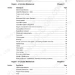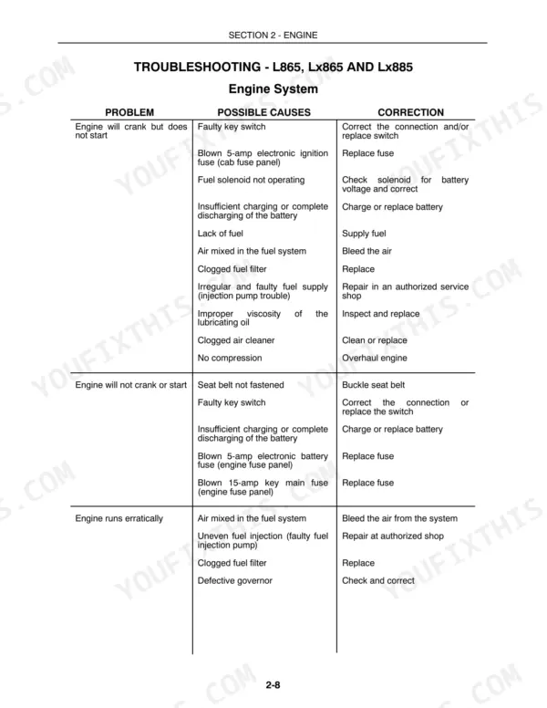

Part of the New Holland Repair Manuals.
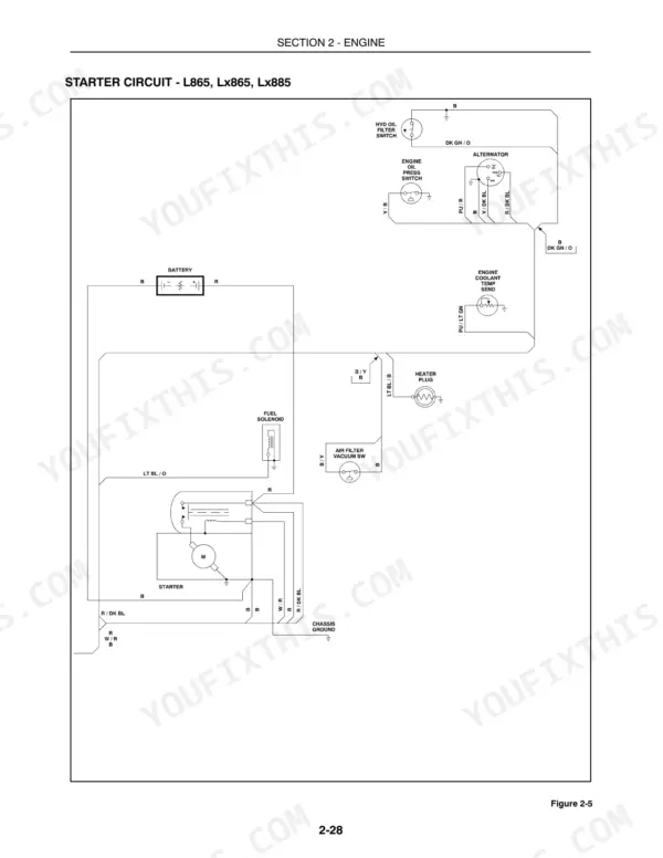
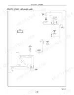
Pulling the wrench work for four skid-steer loader models into one 1000-page book, this New Holland LX865 repair manual PDF covers the whole family, L865 through LX985. Full wiring diagrams anchor the electrical section, tracing every circuit from the accessory relay and engine fuse block out through the harness connectors. Hydrostatic drive testing gets its own chapter, with pump and charge-pump procedures that end in a pass-or-replace verdict, and the hydraulic schematics carry through the loader control valve to the auxiliary and high-flow boom circuits. Before you condemn a starter, check the fuse block against the printed values, 10A on fuse 1 and 25A on fuse 2, then torque the turbocharger to its manifold at 41-47 N·m. Some days it's you, the loader, and nobody to ask. This PDF travels wherever the machine sits, bookmarked by system and searchable by keyword, ready when you are.
What's Inside This Repair Manual
| System | Pages | Key Topics |
|---|---|---|
| General Information | 4-47 | Introduction, Improvements, Precautionary Statements (Personal Safety, Machine Safety), Safety Precautions, Safety Decals, Model and Serial Number Location |
| Engine | 48-295 | Safety Precautions, Engine Service, Troubleshooting |
| Electrical System | 296-486 | General Electrical Information, Definition of Terms, Wiring Diagrams |
| Final Drive, Axles, Brakes, Gearboxes | 487-558 | Troubleshooting, Axles |
| Hydrostatic System and Steering System | 559-706 | Hydrostatic Drive System Testing, Hydrostatic and Charge Pumps |
| Hydraulic System | 707-828 | Hydraulic System Testing, Control Valve |
| Seat, Cab, ROPS, Boom Lock, Boom, Attachment Mounting Plate | 829-914 | Boom Lock Pin Linkage, Attachment Mounting Plate |
| Optional Equipment | 915-1000 | Auxiliary Boom Hydraulics, High-Flow Hydraulics |
Quick Reference Specifications
| Specification | Value | Page |
|---|---|---|
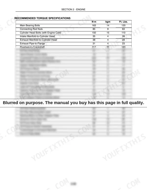
| Turbine Housing Bolts | 20-25 N·m | p. 76 |
| Turbocharger to Manifold | 41-47 N·m | p. 76 |
| Voltage | 0.5 to 1.0 volt below battery voltage | p. 422 |
| Fuse 1 | 10A | p. 424 |
| Fuse 2 | 25A | p. 424 |
| Alternator Excite Resistor Resistance | 50 ohms ± 5 ohms | p. 426 |
| Seat Switch Fuse | 5A | p. 424 |
| solenoid coil torque | 15 N·m (11 ft. lbs.) | p. 443 |
| Wire harness (main), remove and replace | 6.0 hr. | p. 480 |
| Wire harness (engine), remove and replace | 1.5 hr. | p. 480 |
| Electronic instrument cluster | 0.25 hr. | p. 480 |
| Preheat relay, remove and replace | 0.5 hr. | p. 480 |