
Part of the New Holland Repair Manuals.
When the drive line on an LW170 starts slipping under load, the diagnostics in this service manual tell you in minutes whether the fault sits in the torque converter or the transmission control valve. That is not a call you can make by feel, and the manual walks through the test procedures step by step.
It covers the New Holland LW170 and LW190 wheel loaders with the Cummins C8.3-C engine: 300 pages spanning engine, drive line and transmission, braking, steering, bucket boom and frame, attachment hydraulic system, electrical system and cab, with separate specification sections for each model.
Guessing a boom cylinder lock nut torque or a relief valve setting is how loaders end up with blown seals and cracked castings. The figures here are the factory numbers, and as a PDF the whole book goes wherever the machine is parked.
What's Inside This New Holland LW170, LW190 Manual
| System | Pages | Key Topics |
|---|---|---|
| Safety Rules | 1-20 | Generalities, Maintenance |
| Specifications - Wheel Loader LW170 | 21-24 | Cummins C8.3-C 125 kW, Engine Speeds, Torque Converter and Transmission, Axles and Brakes, Booms and Hydraulic System, Weight and Main Dimensions |
| Specifications - Wheel Loader LW190 | 25-26 | Cummins C8.3-C 150 kW, Tire Sizes, Steering System, Attachment Hydraulic System, Electrical System, Operating Weight and Dimensions |
| Fluids and Capacity Table | 27 | Engine, Transmission, Axles, Fuel Tank |
| Units of Measure Used in the Manual | 28 | Force, Pressure, Torque |
| Tightening Torques | 29-31 | Nuts, Screws, Resistance Class, Material Index, Coating Index |
| Engine | 32-43 | Identification Data, General Specifications, Engine Supports, Series C Engine Diagrams |
| Drive Line/Transmission | 44-119 | General Description, Torque Converter, Transmission Control Valve |
| Braking System | 120-147 | General Description, Operation, Diagnostics and Testing |
| Steering System | 148-175 | General Description, Steering Group, Steering Valve, Steering System Pump |
| Bucket Boom and Frame | 176-187 | General Description, Bucket Positioner Device |
| Attachment Hydraulic System | 188-225 | General Description, Hydraulic System Pump, Equipment Control Valve |
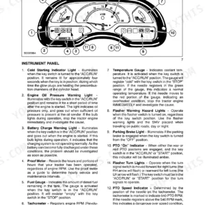
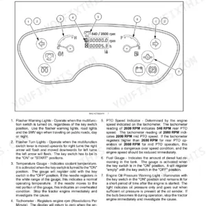
| Electrical System | 226-289 | Logic Board, Cab Instruments Cluster, Connectors |
| Cab | 290-300 | General Description, Repair, Cab Glazing |
Quick Reference Specifications
| Specification | Value | Page |
|---|---|---|
| All Models | ||
| Wheel tightening torque | 78.8 daNm | p. 21 |
| Delco starter motor rated power | 41MT- 24V - 7.5 kW | p. 22 |
| Engine support screw torque | 22.4 daNm | p. 39 |
| Engine support screw torque (LW190) | 8.8 daNm | p. 39 |
| Restriction of fuel filter (maximum pressure drop) | 0.345 bar (35 kPa) [5 psi] | p. 37 |
| Operating pressure of the by-pass valve | 1.75 bar (24.9 psi) | p. 104 |
| Engine Oil Capacity | 23.8 L | p. 27 |
| Cooling System Capacity | 45 L | p. 27 |
| LW170 | ||
| Transmission Oil Capacity | 20 L | p. 27 |
| Fuel Tank Capacity | 220 L | p. 27 |
| Loader Operating Weight | 13900 kg | p. 22 |
| LW190 | ||
| Fuel Tank Capacity | 240 L | p. 27 |
New Holland LW170, LW190 Common Problems This Manual Covers
Loader slips or loses drive under load
A loader that stalls out on the pile or creeps uphill usually has a torque converter or transmission control valve problem. The Drive Line/Transmission section gives the general description, converter operation and control valve procedures needed to isolate which one is at fault.
Manual Section: Drive Line/Transmission p. 44Slow or weak boom and bucket hydraulics
Long lift cycles and a bucket that will not break out point to a tired hydraulic pump or a main relief valve drifting off its 206 bar setting. The Attachment Hydraulic System section covers the pump and equipment control valve so you can test before replacing parts.
Manual Section: Attachment Hydraulic System p. 188Brakes drag or pedal goes soft
Lost accumulator pre-charge (45 bar in this system) shows up as a dead pedal or brakes that will not release cleanly. The Braking System section includes operation, diagnostics and testing procedures to trace the circuit rather than swap components blind.
Manual Section: Braking System p. 120Heavy or wandering steering
Steering that gets stiff at idle or wanders on the haul road typically comes back to the steering system pump or the steering valve. This manual describes the steering group, valve and pump with the procedures to pin down internal leakage.
Manual Section: Steering System p. 148Bucket positioner stops returning to dig
When the bucket no longer levels itself after dumping, the bucket positioner device needs checking and adjusting. The Bucket Boom and Frame section covers the positioner along with the boom and frame structure it mounts to.
Manual Section: Bucket Boom and Frame p. 176Warning lights and electrical faults
Intermittent gauges and warning lamps on these loaders often trace to connectors or the logic board rather than the component itself. The Electrical System section documents the logic board, cab instrument cluster and connectors so you can chase the circuit end to end.
Manual Section: Electrical System p. 226Cummins engine overheats or starves for fuel
Power loss under load on the C8.3-C is often nothing more than a restricted fuel filter, and overheating starts with the cooling circuit. The Engine section provides identification data, general specifications and the Series C engine diagrams to work through both.
Manual Section: Engine p. 32Frequently Asked Questions
Does this manual cover both the LW170 and the LW190?
Yes. It has separate specification sections for each model, covering engine, engine speeds, torque converter, transmission, axles and brakes, and both machines use the Cummins C8.3-C engine. The repair sections apply to both loaders. p. 21
Are hydraulic pressure test values included?
Yes. The Attachment Hydraulic System section lists working settings such as the 206 bar main relief valve and the 30 bar control circuit pressure, along with pump and equipment control valve procedures for testing them. p. 188
Where do I find fluid capacities?
The Fluids and Capacity Table covers engine oil (23.8 L), cooling system (45 L), transmission, hydraulic and brake system, axles and fuel tank (220 L for the LW170 and 240 L for the LW190). p. 27
What do I get after purchasing this New Holland LW170 manual?
Instant PDF download. You get the full 300-page searchable Service Manual immediately after payment. Open it on your laptop, tablet, or phone right in the shop.
Can I print a copy of this New Holland LW170 Service Manual for the shop?
You can. The PDF is unlocked and carries no copy protection, so print the sections you want and keep the file as your backup.







Reviews
There are no reviews yet.