

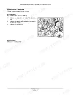
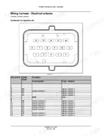
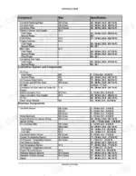
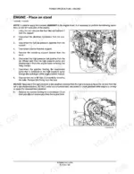
Part of the New Holland Repair Manuals.
Back off the rocker on a cold NEF and the feeler gauge has to come out at 0.20 to 0.30 mm on the intake and 0.45 to 0.55 mm on the exhaust. Those figures sit on page 47, next to the thermostat opening range and the common rail injection pressure.
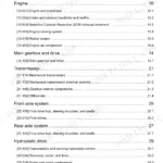
This is New Holland publication 84250493, 472 pages, covering the F4CE9484, F4CE9684, F4DE9484, F4DE9684, F4DE9687, F4GE9484, F4GE9684, F4HE9484 and F4HE9684 in both four and six cylinder form. Chapters run from valve drive and camshaft, through connecting rod, piston and flywheel, cylinder head and timing gear housing, fuel and injection, air intake and exhaust, coolant and lubrication, to the starting system.
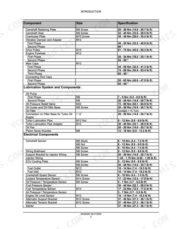
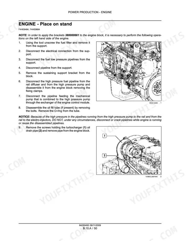
With the engine on a stand, the torque tables in the Introduction settle the cylinder head, main cap, rod cap and oil pump sequences before anything is buttoned up, and the Engine section carries the removal, check and installation steps for each assembly.
What's Inside This New Holland NEF Tier 3 Manual
| System | Pages | Key Topics |
|---|---|---|
| Introduction | 1-27 | Safety Rules, Torque Specifications, Special Tools |
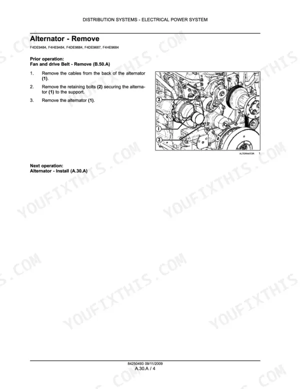
| Distribution Systems | 28-37 | Electrical Power System |
| Engine - General Specifications and Maintenance | 38-65 | General Specifications, Service Limits, Maintenance Planning, Component Localisation |
| Engine - Valve Drive and Camshaft | 66-160 | Valve Drive, Camshaft, Rocker Assembly, Valve Assembly, Auxiliary Drive, Crankshaft |
| Engine - Connecting Rod, Piston, and Flywheel | 161-213 | Connecting Rod, Piston, Flywheel, Vibration Damper, Balancer, Cylinder Block |
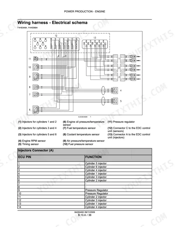
| Engine - Cylinder Head and Timing Gear Housing | 214-269 | Cylinder Head, Timing Gear Housing, Wiring Harness, Electronic Control, Sensing System |
| Fuel and Injection System | 270-355 | Fuel Injection Pump, Water Separator, Electro Injector, High Pressure Common Rail, Fuel Heater |
| Air Intake and Exhaust Systems | 356-379 | Turbocharger, Air Intake Manifold, Exhaust Manifold, Exhaust Gas Re-Circulation |
| Engine Coolant and Lubrication Systems | 380-461 | Thermostat, Water Pump, Water Manifold, Fan and Drive Belt, Oil Pump, Oil Pan, Oil Cooler |
| Starting System | 462-472 | Cold Start Aid, Grid Heater, Engine Starter |
Quick Reference Specifications
| Specification | Value | Page |
|---|---|---|
| All Models | ||
| Fuel filter tightening torque | 10 - 15 Nm (7 - 11 lb ft) | p. 98 |
| Fuel Pressure Sensor | 30 - 40 Nm | p. 10 |
| High-pressure fuel pump gear nut torque | 90 - 95 Nm (66.4 - 70.1 lb ft) | p. 316 |
| Impedance of the coil of each injector | 0.56 - 0.57 Ω | p. 286 |
| Coolant Temperature Sensor | 17 - 23 Nm | p. 10 |
| Crankshaft sensor impedance | ~900 Ω | p. 82 |
| Camshaft speed sensor impedance | ~900 Ω | p. 83 |
| Fuel pressure sensor power supply | 5 Volt | p. 305 |
| Pumping element pre-lift (4 Cylinder Engines) | 0.73 - 0.77 mm (0.029 - 0.030 in) | p. 317 |
| F4CE9484, F4GE9484, F4CE9684, F4GE9684 | ||
| Oil pressure sensor working tensions | 12-24 V | p. 429 |
| Oil pressure sensor contact closure upon lower pressure | 0.2 bar (2.9 psi) | p. 429 |
| F4HE9484, F4HE9684 | ||
| Coolant temperature sensor impedance at 20 °C (68 °F) | 2.50 Ω | p. 387 |
New Holland NEF Tier 3 Common Problems This Manual Covers
Low oil pressure warning at idle
A warning lamp at hot idle is as often the sender as the pump. On the F4CE and F4GE engines the switch closes below 0.2 bar (2.9 psi) and opens again above 0.9 bar (13.1 psi), so the lamp can be checked against a mechanical gauge before the pan comes off.
Manual Section: Engine Coolant and Lubrication Systems p. 429Rough idle from a failing electro injector
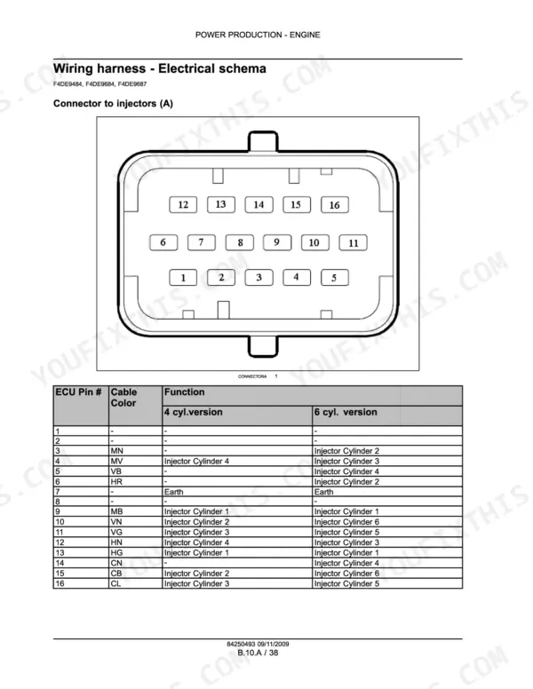
One dead or leaking injector shows up as a miss, white smoke and a fuel knock that moves with load. On the common rail F4DE and F4HE engines the Fuel and Injection System section gives the electro injector coil impedance as 0.56 to 0.57 ohm, which separates an electrical fault from a worn nozzle.
Manual Section: Fuel and Injection System p. 286Cranks but will not fire
A crankshaft speed sensor that has drifted or lost its air gap leaves the ECU with no timing reference. For the F4HE engines the manual gives the crankshaft sensor impedance as about 900 ohms, so a meter at the connector rules it in or out before the injectors are touched.
Manual Section: Engine - Valve Drive and Camshaft p. 82Overheating and a slow warm-up
A thermostat stuck part open never lets the engine reach temperature, and one stuck shut boils it. The opening range is 79 to 83 degrees C, which is the figure to test against in a pan of water before blaming the water pump or radiator.
Manual Section: Engine Coolant and Lubrication Systems p. 47Head gasket failure after an overheat
Combustion gas in the coolant or coolant in the oil means the head has to come off. The Engine section covers cylinder head removal, a block deck planarity check, valve seat and guide inspection, and the staged bolt tightening sequence for reassembly.
Manual Section: Engine - Cylinder Head and Timing Gear Housing p. 215Oil consumption and blue smoke
Worn rings, a glazed bore or a tired turbo seal all read as oil burn. The Engine section gives piston ring removal, measurement and installation and piston pin measurement, so the block can be measured and judged instead of guessed at by symptom.
Manual Section: Engine - Connecting Rod, Piston, and Flywheel p. 161Poor cold starting on a grid heater engine
Long cranking and heavy white smoke on a cold morning often trace to the intake grid heater or its contactor. The Starting System section describes the grid heater and its contactor, and covers the starter by removal and installation.
Manual Section: Starting System p. 462Frequently Asked Questions
Which NEF engines does this manual cover?
Nine variants: F4CE9484, F4CE9684, F4DE9484, F4DE9684, F4DE9687, F4GE9484, F4GE9684, F4HE9484 and F4HE9684, in four and six cylinder form. It is New Holland publication 84250493, 472 pages. Specification tables call out which figures apply to which engine family.
What is the cylinder head bolt torque sequence for a New Holland NEF Tier 3 engine?
For the F4DE9484, F4HE9484, F4DE9684, F4DE9687 and F4HE9684 with M12x1.75x130 mm bolts, the sequence is 30 to 40 Nm first, then 85 to 95 degrees, then a further 85 to 95 degrees. Main cap and connecting rod cap phases follow on page 10. p. 9
How much oil does the NEF Tier 3 engine sump hold?
The F4DE general specification table lists an oil pan capacity of 15 l, and the F4HE table on page 47 prints the same figure. The same tables carry the thermostat range and injection pressure. p. 52
Does it cover the common rail fuel system?
Yes for the F4DE and F4HE engines: the Fuel and Injection System section starts at page 270 with common rail overviews and electro injector and fuel manifold removal and installation. p. 270
How will I receive this New Holland NEF Service Manual?
You get a 472-page searchable PDF that downloads instantly after checkout. Open it on your laptop, tablet, or phone, and bring it right to the shop floor.
Am I able to print pages from this New Holland NEF manual?
Zero restrictions. The PDF is DRM-free. Print whatever sections you need to take out to the shop. Standard letter or A4 paper works.






Reviews
There are no reviews yet.