Part of the New Holland Repair Manuals.
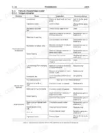
A directional clutch that will not hold pressure gives you nothing to work with until someone hands you the figure it is supposed to make, and that number sits in the 389 pages of this New Holland LW270 service manual, next to the oil flow diagrams that explain where the pressure went.
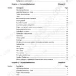
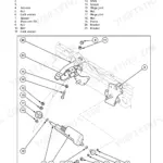
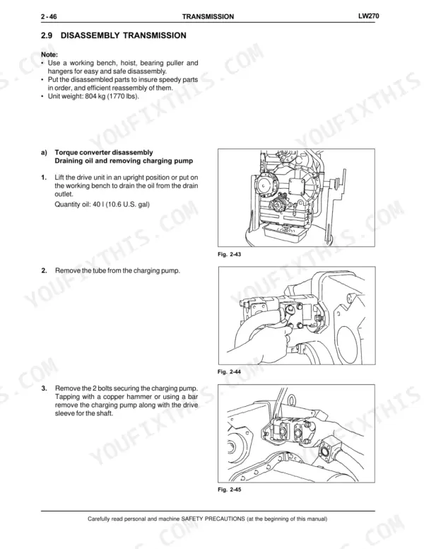
Publication 75131020 is written for the LW270 wheel loader with the Cummins M11C engine. It runs from safety rules, specifications and fluid capacities through the engine, torque converter and transmission, front and rear axles, braking, steering, the bucket boom and frame, the attachment hydraulic system, the electrical system and the cab.
Most jobs stall for want of one figure: a clearance, a test pressure, a tightening torque. This book carries them section by section with the disassembly and reassembly steps built around them. Download the PDF, print only the pages the job needs, and let them get dirty on the bench.
What's Inside This Manual
| System | Pages | Key Topics |
|---|---|---|
| Safety Rules | 14-20 | Generalities |
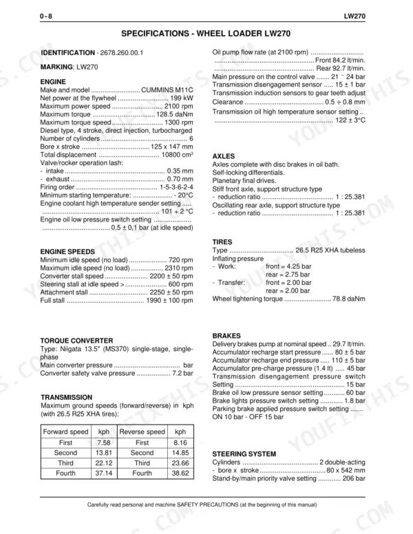
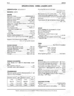
| Specifications | 21-22 | Engine, Torque Converter, Axles, Tires, Brakes, Steering System |
| Fluids and Capacity Table | 23 | Engine, Cooling System, Transmission, Hydraulic and Brake System, Fuel Tank |
| Units of Measure Used in the Manual | 24 | Force, Pressure, Torque |
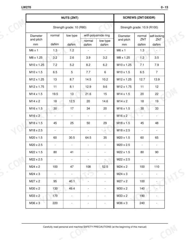
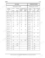
| Tightening Torques | 25-27 | Torque Converter, Transmission, Nuts, Screws |
| Engine | 28-37 | Identification Data, General Specifications, Engine Supports |
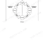
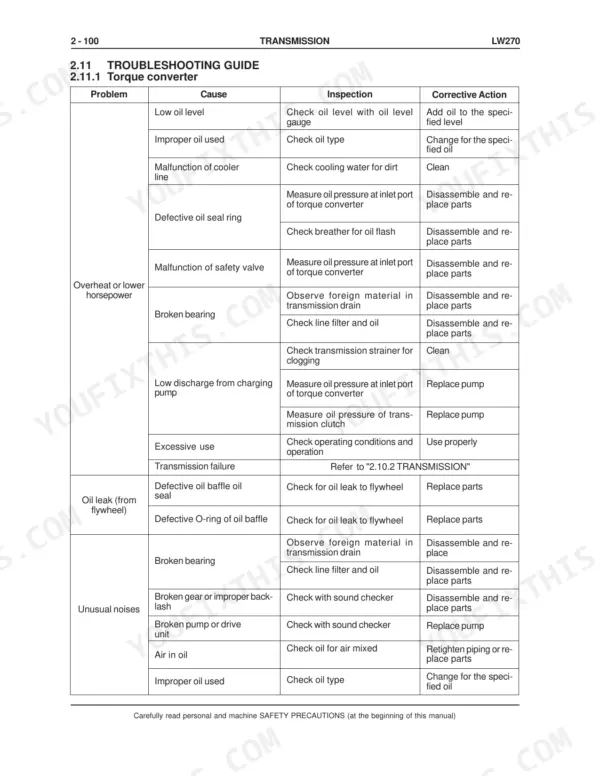
| Transmission General Description and Torque Converter | 38-50 | General Description, Power Train Diagram, Torque Converter Operation, Oil Flow |
| Transmission Pump and Directional Clutches | 51-55 | Torque Converter Pump, Directional Clutches Shaft, Clutch Engagement Operation, 2nd Speed Clutch Accumulator |
| Power Train Diagrams and Control Valve | 56-72 | Forward/Reverse Power Train Diagrams, Transmission Control Valve, Solenoid Valve Operation, Manual Spool Emergency Travel |
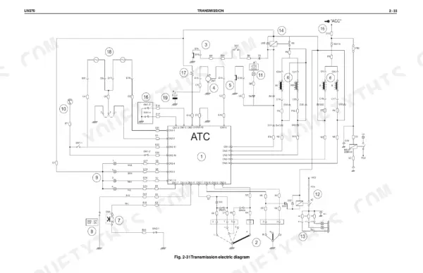
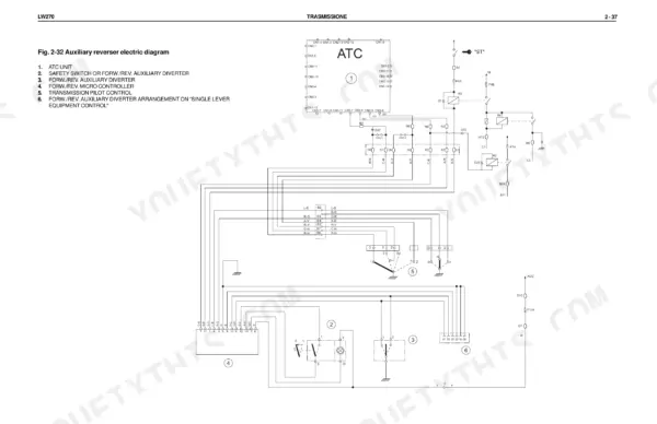
| Automatic Transmission Control System | 73-84 | ATC Electronic Unit, Wiring Diagrams, Transmission Selector, Kick-Down Function |
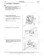
| Oil Circuit and Transmission Disassembly | 85-109 | Transmission Oil Circuit, Delivery Filter, Disassembly Procedures, Parking Brake Disassembly |
| Transmission Reassembly and Maintenance Values | 110-150 | Reassembly Procedures, Standard Maintenance Values, Tightening Torques, Prop Shafts |
| Front and Rear Axles | 151-195 | Axle Description, Differential Operation, Final Drives, Axle Disassembly and Reassembly, Troubleshooting |
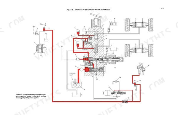
| Braking System | 196-221 | General Description, Operation, Diagnostics and Testing |
| Steering System | 222-245 | General Description, Steering Group, Steering Valve |
| Bucket Boom and Frame | 246-259 | General Description, Bucket, Bucket Positioner Device |
| Attachment Hydraulic System | 260-297 | General Description, Hydraulic System Pump, Equipment Control Valve |
| Electrical System | 298-353 | Logic Board and Cab Connections, Cab Instruments Cluster, Connectors |
| Cab | 354-389 | General Description, Repair, Air Conditioning Unit |
Quick Reference Specifications
| Specification | Value | Page |
|---|---|---|
| Wheel tightening torque | 78.8 daNm | p. 21 |
| Low pressure switch interruption | OFF 2,45 bar, ON 2,6 bar | p. 367 |
| High pressure switch interruption | OFF 28 bar, ON 25 bar | p. 367 |
| Steering valve main pressure setting | 206 bar (2980 psi) | p. 230 |
| Steering valve safety and anticavitation valve setting | 245 bar (3550 psi) | p. 230 |
| Thermostat range | 82 - 93°C [180° to 200°F] | p. 32 |
| Coolant pressure in cylinder block (Minimum, Thermostat closed - 1800 rpm - no load) | 1.37 bar (138 kPa) [20 psi] | p. 32 |
| Transmission-torque converter group support bracket to engine | 18 daNm | p. 43 |
| Clutch engagement oil pressure | 21 - 24 bar (299 - 342 psi) | p. 44 |
| Opening pressure of safety valve | 7.2 bar (102 psi) | p. 44 |
| Front windscreen wiper motor stroke | 45° | p. 359 |
| Rear windscreen wiper motor oscillation | 80° | p. 359 |