It is seeding season, the 900 is parked at the headland with the implement hydraulics gone soft, and the dealer is an hour each way. This operator manual for the Versatile Series 2 Model 900 four wheel drive tractor tells you where to start: the hydraulic and transmission filters and suction screens, the relief and flow control valve settings, and a troubleshooting section aimed at steering, implement control and engine complaints.
Sixty-six pages cover the tractor as it is built around the Cummins V-903 V8 diesel: controls and instruments, starting and shifting, three-point hitch and remote hydraulics, tire inflation and ballast, fuels and lubricants, routine service intervals, storage, the electrical system with fuses and wiring diagrams, and the full system schematics.
Buy it once, print the pages you want to keep on the bench, and it stays yours for as long as you own the tractor.
What's Inside This Versatile Series 2 Model 900 Operator Manual
| System | Pages | Key Topics |
|---|---|---|
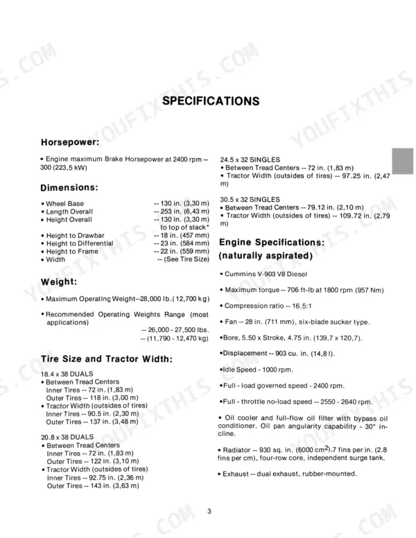
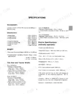
| Specifications | 7-9 | Horsepower, Engine Specifications, Transmission, Hydraulics, Electrical, Cab |
| Safety Rules | 10-11 | Fire Extinguisher, Seat Belt, Hitching, Hydraulic Pressure, Batteries |
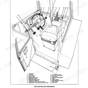
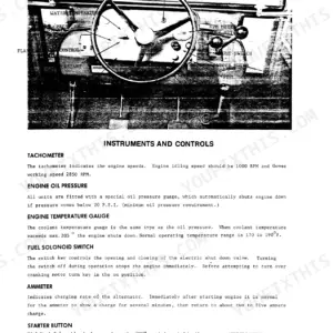
| Controls and Instruments | 12-18 | Light Switch, Tachometer, Hydraulic Controls, Three-Point Hitch, Flow Control, Air Intake Control |
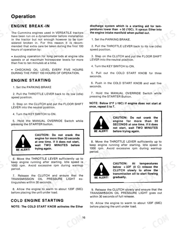
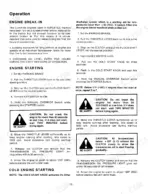
| Operation | 19-27 | Engine Starting, Hydraulics, Shifting Gears, Tire Inflation, Tire Ballast, Three Point Hitch |
| Fuels, Fluids and Lubricants | 28-30 | Fuels, Coolant, Liquid Ballast, Hydraulic Fluid, Lubricants |
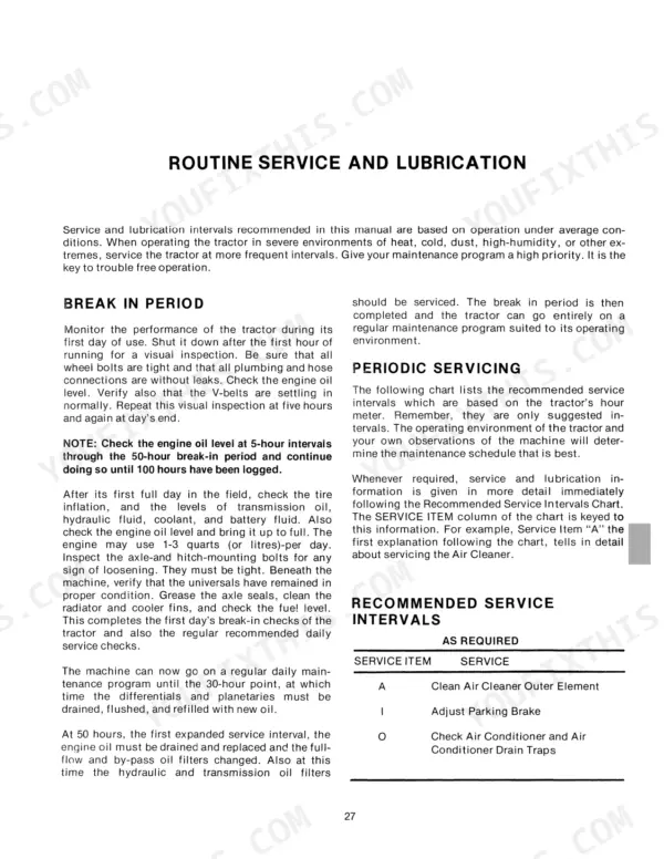
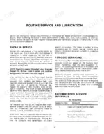
| Routine Service and Lubrication | 31-48 | Air Cleaner, Cooling System, Electrical System, Hydraulic Filters, Transmission Filters, Fuel System Maintenance |
| Troubleshooting | 49-51 | Steering, Implement Control, Hydraulic Oil, Cab Comfort System, Engine |
| Storage and Preparation | 52-53 | Storing the Tractor, Preparation of Engine, Storing Batteries, Preparation After Storage, Startup of Engine |
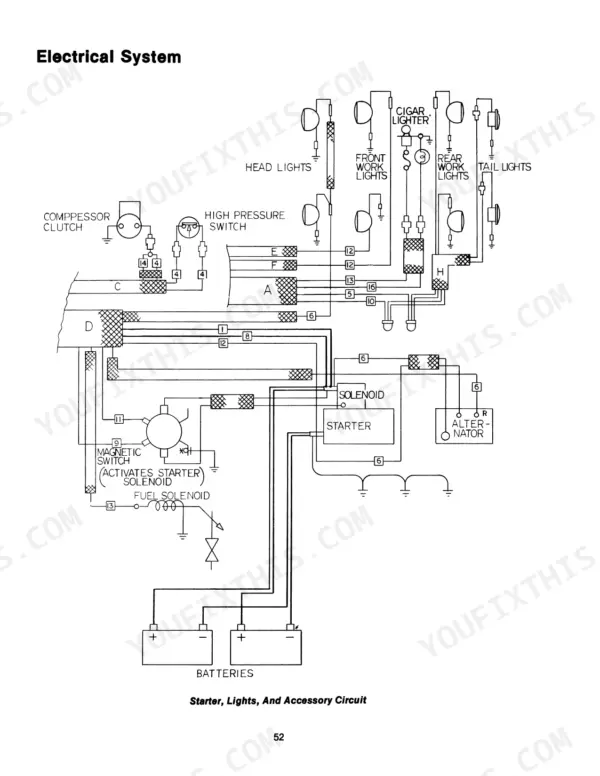
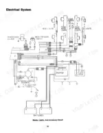
| Electrical System | 54-58 | Fuses, Circuit Breakers, Wiring Diagram, Starter Circuit, Lighting Circuit, Cab Console Circuit |
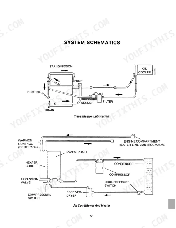
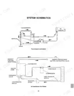
| System Schematics | 59-66 | Transmission Lubrication, Air Conditioner, Heater, Steering Circuit, Implement Circuit, Three-Point Hitch Hydraulics |
Quick Reference Specifications
| Specification | Value | Page |
|---|---|---|
| Maximum torque | 706 ft-lb at 1800 rpm (957 Nm) | p. 7 |
| Relief valve (tank mounted) set | 2300 + 50 psi (15.86 MPa + 340 kPa) | p. 8 |
| Two four-way self-cancelling spools set | 2100 + 0-100 psi (14,48 MPa + 0-690 kPa) | p. 8 |
| Air cleaner restriction gauge cleaning threshold | 20-in. (51 cm) | p. 34 |
| Air cleaner outer element max cleaning air pressure | 100 psi (690 kPa) | p. 34 |
| Wheel bolts torque | 220 ft-lbs (300 N-m) | p. 39 |
| Transmission return oil line filter replacement interval | 200 hours | p. 38 |
| Hydraulic suction screen cleaning interval | 400 hours | p. 38 |
| Engine maximum Brake Horsepower | 300 (223.5 kW) | p. 7 |
| Maximum Operating Weight | 28,000 lbs (12,700 kg) | p. 7 |
| Engine Maximum Torque | 706 ft-lb at 1800 rpm (957 Nm) | p. 7 |
| Engine Idle Speed | 1000 rpm | p. 7 |